Calculating method for determining gas content of gas-liquid two-phase flow in ladle

A technology of gas-liquid two-phase flow and calculation method, which is applied in the simulation field of hot metal pretreatment and desulfurization process, and can solve the problems of less calculation and the inability to verify the gas-liquid two-phase flow in the ladle

Active Publication Date: 2018-09-14
NORTHEASTERN UNIV
View PDF3 Cites 4 Cited by
  • Summary
  • Abstract
  • Description
  • Claims
  • Application Information

AI Technical Summary

Problems solved by technology

[0004] At present, there are few calculations on gas-liquid two-phase flow gas holdup in ladle, and gas-liquid two-phase flow in ladle cannot be verified, so it is necessary to establish a simulation to describe gas holdup in ladle-water model method, calculate the gas holdup and overflow velocity of the gas at the outlet of the ladle, analyze the a

Method used


Image

  • Calculating method for determining gas content of gas-liquid two-phase flow in ladle
  • Calculating method for determining gas content of gas-liquid two-phase flow in ladle
  • Calculating method for determining gas content of gas-liquid two-phase flow in ladle

Examples


Embodiment 1

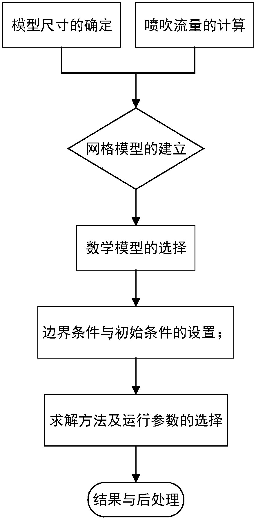
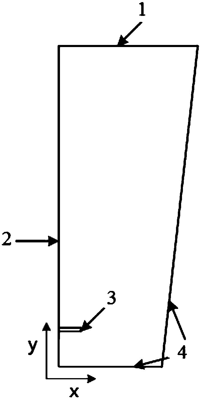
[0090] The numerical simulation method of the gas-liquid two-phase flow gas holdup in the ladle-water model, (wherein the present invention adopts the blowing desulfurization method, and the spray gun adopts an inverted "T" type spray gun) comprises the following steps:

[0091] Step 1. Collection of process parameters: On-site investigation of the steelmaking workshop of a steel factory to obtain the process parameters of the ladle during the actual production process, including: diameter of the upper mouth of the ladle, diameter of the bottom of the ladle, height of the ladle, depth of spray gun insertion, nozzle Diameter, injection flow rate of magnesium powder and carrier gas flow rate.

[0092] Step 2. Calculation of the size of the water model: According to the process parameters collected in step 1, including the diameter of the upper mouth of the ladle, the diameter of the bottom of the ladle, the height of the ladle, the insertion depth of the spray gun, and the diamet...

Embodiment 2

[0157] Step 1. Collection of process parameters: On-site investigation of the steelmaking workshop of a steel factory to obtain process parameters in the actual production process, including: diameter of the upper mouth of the ladle, diameter of the bottom of the ladle, height of the ladle, depth of spray gun insertion, diameter of the nozzle, Magnesium powder injection flow rate and carrier gas flow rate. Its specific data are shown in Table 1:

[0158] Table 1 process parameters

[0159]

[0160]Step 2. Calculation of the size of the water model: According to the process parameters collected in step 1, including the diameter of the upper opening of the ladle, the diameter of the bottom of the ladle, the height of the ladle, the insertion depth of the spray gun, and the diameter of the nozzle, the water model is determined based on the geometric similarity theory The geometric size of the water model, the similarity ratio is 1:5, that is, the size is reduced by 1:5, and t...


PUM


Abstract

The invention relates to a calculating method for determining the gas content of gas-liquid two-phase flow in a ladle. The method includes the steps of determining a two-dimensional geological model of a water model according to actual technological parameters of the ladle, determining the gas injection flow Qm in the water model, establishing a gas-liquid two-phase flow model and a gas-liquid interaction force model, and obtaining a distribution map of the gas content in the water model and a gas-liquid phase flow field. By means of the method, the gas content and overflow speed of gas in anoutlet of the ladle can be calculated, the liquid-phase injection amount caused by gas overflow is analyzed, the influences of the gas flow of an injection gun and the insertion depth of the injectiongun on the gas content, the overflow speed and the injection amount can be detected by changing the gas flow of the injection gun and the insertion depth of the injection gun, all the technological parameters are accurately adjusted in real time, and the accident occurrence rate is reduced.

Description

technical field [0001] The invention relates to a calculation method for determining the gas holdup of a gas-liquid two-phase flow in a molten iron ladle, and belongs to the simulation field of the pretreatment desulfurization process of molten iron. Background technique [0002] With the development of the steel industry, processing manufacturing industry and steel-related industries, steel users have higher and higher requirements for steel quality. Sulfur, as a major harmful element in steel, not only tends to cause hot embrittlement of steel, reduces the ductility, toughness and corrosion resistance of steel, but also tends to cause cracks in steel. Therefore, the content of sulfur element should be controlled as much as possible to ensure the quality of steel. Hot metal pretreatment desulfurization technology not only has good desulfurization effect, but also has low desulfurization cost, so hot metal pretreatment technology has become an essential link in the producti...

Claims


Application Information

Patent Timeline
IPC IPC(8): G06F17/50
CPCG06F30/20
Inventor 郑淑国王鑫朱苗勇
Owner NORTHEASTERN UNIV
Why Eureka
Try Eureka