Rectangular double-ridge-waveguide torsional transmission line

A double-ridged waveguide and transmission line technology, used in waveguides, waveguide-type devices, electrical components, etc., can solve the problems of complex matching circuit structure, narrow bandwidth, large volume, etc., and achieve obvious advantages and improve the effect of modeling optimization and calculation efficiency.

Inactive Publication Date: 2018-09-14
成都锐烽特科技有限公司
View PDF2 Cites 0 Cited by
  • Summary
  • Abstract
  • Description
  • Claims
  • Application Information

AI Technical Summary

Problems solved by technology

[0003] The existing matching circuit has complex structure, large volume, and narrow bandwidth, especially in rectangular waveguides, single-ridge rectangular waveguides, double-ridge rectangular waveguides and four-ridge rectangular waveguides, circular waveguides or elliptical waveguides, single-ridge circular waveguides or elliptical waveguides, Double-ridge circular or elliptical waveguides, and four-ridge circular or elliptical waveguides in

Method used


Image

  • Rectangular double-ridge-waveguide torsional transmission line
  • Rectangular double-ridge-waveguide torsional transmission line
  • Rectangular double-ridge-waveguide torsional transmission line

Examples


Embodiment 1

[0030] Such as Figure 1a , Figure 1b and figure 2 shown.

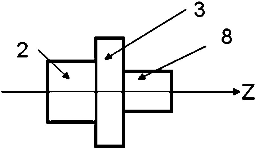
[0031] A rectangular double ridge waveguide twisted transmission line, including an input transmission line 2 and an output transmission line 8 sequentially connected along the Z direction, and an electromagnetic channel 3; the two ends of the electromagnetic channel 3 are respectively a plane A and a plane A parallel to each other A part of B; the input transmission line 2 and the output transmission line 8 respectively communicate with one of the two end faces of the electromagnetic channel 3; the electromagnetic channel 3 is formed by a branch.

[0032] The input transmission line 2 and the output transmission line 8 are the same transmission line; the cross-sectional shape of the output transmission line 8 perpendicular to the Z axis and the cross-sectional shape of the input transmission line 2 perpendicular to the Z axis are rotated 90 degrees around the Z axis same.

[0033] The input transmission line 2 a...

Embodiment 2

[0036] Such as Figure 1a , Figure 1b and image 3 shown.

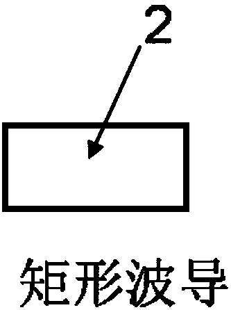
[0037] The main difference between this implementation example and implementation example 1 is that the input transmission line 2 and the output transmission line 8 are the same double-ridge rectangular waveguide.

Embodiment 3

[0039] Such as Figure 4 and 5 shown.

[0040] Further specific realization of this implementation example and implementation example 3. The input transmission line 2 and the output transmission line 8 are the same double-ridge rectangular waveguide.

[0041] The cross-sectional shape of the output transmission line 8 perpendicular to the Z-axis is the same as the cross-sectional shape of the input transmission line 2 perpendicular to the Z-axis after being rotated 90 degrees around the Z-axis.

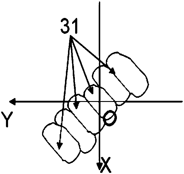
[0042] The electromagnetic channel 3 is formed by a branch. The branch is composed of 17 rectangular through holes communicating with each other through one side thereof. The electromagnetic channel 3 is rotated by 45 degrees around the Z axis.

[0043] The double-ridge rectangular waveguide has a width of 7.7 mm and a height of 3.3 mm. The metal ridge width is 1.93mm. The gap between the tops of the metal ridges is 0.61 mm. Using an electromagnetic channel with a length of on...


PUM


Abstract

The invention discloses a rectangular double-ridge-waveguide torsional transmission line, and the transmission line comprises at least one input transmission line and one output transmission line, andan electromagnetic channel. The input and output transmission lines are each communicated with one of the two end faces of the electromagnetic channel. The output transmission line is determined by the rotating of the input transmission line around the Z-axis by a certain angle. The input transmission line is a rectangular ridge waveguide, and the electromagnetic channel consists of at least onebranch. At least one of the branches is formed by at least three through holes which are communicated in the Y direction. The torsional transmission line can achieve the wideband compact torsional transition of various waveguides, ridge waveguides, and multi-ridge waveguides. The transmission line is mainly used in various communication and radar systems of microwaves, millimeter waves and terahertz bands.

Description

technical field [0001] The invention relates to an electromagnetic wave element, in particular to an electromagnetic wave structure for matching and connecting two transmission lines twisted at a certain angle around an axis. Background technique [0002] In various electromagnetic wave systems, torsional connections of transmission lines around their axes are ubiquitous. The signal in the transmission line will be reflected due to the parasitic effect introduced by the twist of the transmission line. In order to realize the matching of the twisted transmission line, it is necessary to set a matching structure on the transmission line. [0003] The existing matching circuit has complex structure, large volume, and narrow bandwidth, especially in rectangular waveguides, single-ridge rectangular waveguides, double-ridge rectangular waveguides and four-ridge rectangular waveguides, circular waveguides or elliptical waveguides, single-ridge circular waveguides or elliptical wav...

Claims


Application Information

Patent Timeline
Patent Type & Authority Applications(China)
IPC IPC(8): H01P3/12H01P3/123H01P5/00
CPCH01P3/12H01P3/123H01P5/00
Inventor 王清源
Owner 成都锐烽特科技有限公司
Why Eureka
Try Eureka