Check patentability & draft patents in minutes with Patsnap Eureka AI!

Industrial automatic cutting device

A cutting device and industrial technology, applied in the direction of shearing devices, shearing machine accessories, shearing machine equipment, etc., can solve the problem of different degrees of deformation of the cut parts of the rotating metal sheet, affecting the accuracy of experimental analysis, and relatively large internal structure changes. Large and other problems, to achieve the effect of improving accuracy, low cost, reducing load changes and local deformation

Inactive Publication Date: 2018-09-18
宁波隆锐机械制造有限公司
View PDF8 Cites 0 Cited by
  • Summary
  • Abstract
  • Description
  • Claims
  • Application Information

AI Technical Summary

Problems solved by technology

[0004] During the implementation of the above-mentioned technical solution, technicians can extend the length of the cutting knife to adapt to the wide metal sheet, but since the connecting rod is installed on the machine base, the rotation center of the connecting rod is fixed, and the upper cutting on the connecting rod The knife rotates around a fixed center, causing the cutting angle of the upper cutter to gradually decrease when cutting the metal sheet, that is, the load on the shearing part of the metal sheet is always changing, resulting in a large change in the internal structure of the metal sheet cutting part, cutting Changing the angle all the time will easily lead to different deformation degrees of the cut parts of the rotating metal sheet, which also affects the accuracy of the experimental analysis

Method used


Image

  • Industrial automatic cutting device
  • Industrial automatic cutting device
  • Industrial automatic cutting device

Examples


Embodiment Construction

[0019] The following is further described in detail through specific implementation methods:

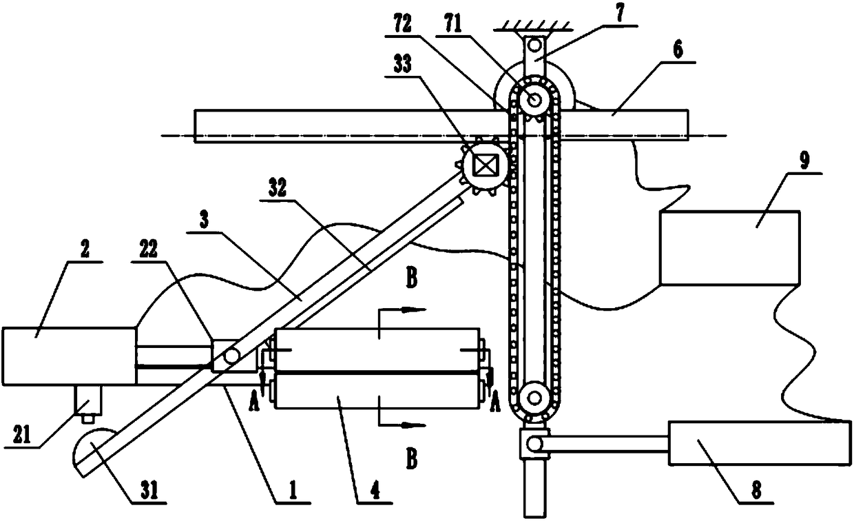
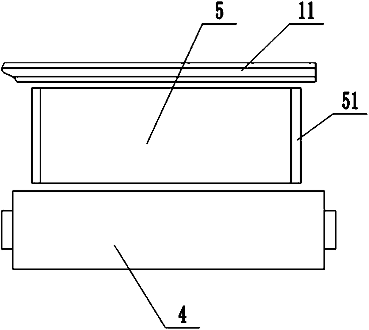
[0020] The reference signs in the accompanying drawings of the description include: cutting table 1, cutting groove 11, first push cylinder 2, booster valve 21, mounting block 22, connecting rod 3, spherical protrusion 31, cutter 32, driving sprocket 33 , Transport roller 4, guide groove 5, protective plate 51, limit rack 6, installation rod 7, transmission sprocket 71, chain 72, second push cylinder 8, central controller 9.

[0021] The embodiment is basically as attached figure 1 Shown:

[0022] The industrial automatic cutting device among the present invention comprises a pair of conveying rollers 4 arranged oppositely, connecting rod 3 and cutting platform 1, leave the gap that is used to pass through for the cutting piece between two conveying rollers 4, one side of this gap Opposite to the cutting table 1, the connecting rod 3 is arranged directly above the cutting table 1, ...


PUM


Abstract

The invention relates to a shearing device and particularly discloses an industrial automatic cutting device comprising a pair of oppositely arranged conveying rollers, a connecting rod and a cuttingtable. A gap is reserved between the two conveying rollers, and a to-be-cut part can pass through the gap. One side of the gap is opposite to the cutting table. The connecting rod is arranged over thecutting table. Cutters are installed on the connecting rod along the rod surface. The industrial automatic cutting device is characterized by further comprising a first pushing oil cylinder, a secondpushing oil cylinder and a transmission chain structure; the first pushing oil cylinder is fixedly connected to the cutting table; the pushing end of the first pushing oil cylinder is hinged to the connecting rod; and a button type pressure increasing valve is installed on the first pushing oil cylinder and is located on the rotation path of the end, away from the cutters, of the connecting rod.According to the technical scheme, the cutting angles of the cutters are adjusted periodically, thus the cutting angle of the whole cutting process is limited within a fixed range, load change and local deformation of the cut position of a metal sheet are reduced, and precision of metal surface analysis is promoted.

Description

technical field [0001] The invention belongs to the technical field with an international classification number of B23D15, and in particular relates to a shearing device. Background technique [0002] In the experiment on the analysis of large-area stainless steel flake surface samples, due to the large size of the metal flakes, the experiment cannot be carried out directly, and the number is difficult to meet the experimental needs. According to the experimental sample rules, large-sized flake samples can be cut and prepared into uniform samples for experiments. In order to reduce the sampling amount and ensure the accuracy of the experimental results, the size of the sample needs to be small and the uniformity should be good. During the sample preparation process, impurities should not be mixed and the shape of the sample should not be changed. Therefore, the requirements for sample preparation are very stringent. [0003] Based on the above technical problems, the Chine...

Claims


Application Information

Patent Timeline
Patent Type & Authority Applications(China)
IPC IPC(8): B23D15/04B23D15/14B23D33/02B23D33/10
CPCB23D15/04B23D15/14B23D33/02B23D33/10
Inventor 李新平
Owner 宁波隆锐机械制造有限公司
Features
  • R&D
  • Intellectual Property
  • Life Sciences
  • Materials
  • Tech Scout
  • Unparalleled Data Quality
  • Higher Quality Content
  • 60% Fewer Hallucinations
Learn More