New-energy automobile device

A new energy vehicle and equipment technology, applied in vehicle components, control devices, transportation and packaging, etc., can solve problems such as the unavoidable current overload loss or damage of the automotive motor coil, the inability to realize the transmission of driving force, and the protection of the automotive motor. Compact structure, solve over-current loss or damage, fast and stable transmission ratio

Active Publication Date: 2018-09-18
江苏贝肯盛创新能源科技有限公司
View PDF6 Cites 0 Cited by
  • Summary
  • Abstract
  • Description
  • Claims
  • Application Information

AI Technical Summary

Problems solved by technology

This invention cannot realize the cushioning transition of the driving force when the driving force of the automobile motor changes suddenly, cannot protect the automobile motor from the mechanical structure, cannot avoid the current overload loss or damage of the automobile motor coil, and cannot realize fast and stable driving force transmission

Method used


Image

  • New-energy automobile device
  • New-energy automobile device
  • New-energy automobile device

Examples


specific Embodiment approach 1

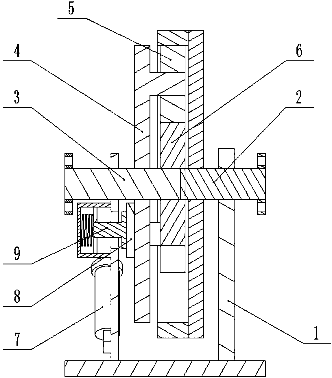
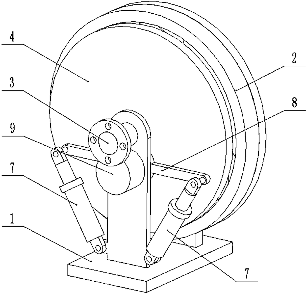
[0027] Combine below Figure 1-9 Describe this embodiment, a new energy vehicle equipment, including drive shaft frame 1, output shaft assembly 2, input shaft 3, intermediate gear frame 4, intermediate gear 5, sun gear 6 and elastic telescopic shaft 7, the output shaft assembly 2 rotatably connected to one end of the drive shaft frame 1, the input shaft 3 is rotatably connected to the other end of the drive shaft frame 1, the intermediate gear frame 4 is rotatably connected to the input shaft 3, and one end of the elastic telescopic shaft 7 is hinged Connected to the eccentric position of the intermediate gear frame 4, the other end of the elastic telescopic shaft 7 is hingedly connected to the drive shaft frame 1, the sun gear 6 is fixedly connected to the input shaft 3, and the intermediate gear 5 is rotatably connected to the intermediate gear frame 4, the intermediate gear 5 meshes with the sun gear 6, and the intermediate gear 5 and the output shaft assembly 2 are connect...

specific Embodiment approach 2

[0028] Combine below Figure 1-9Describe this embodiment, this embodiment will further explain the first embodiment, the friction disc assembly 8 is fixedly connected to the intermediate gear frame 4, the elastic pressing assembly 9 is fixedly connected to the drive shaft frame 1, and the friction disc The component 8 is in frictional contact with the elastic compression component 9; through the elastic compression component 9, the friction disc component 8 is elastically compressed, and when the friction disc component 8 rotates around the input shaft 3 with the intermediate gear frame 4 in a small range, the friction disc component 8 and the elastic compression component The frictional contact of the tight component 9 produces frictional damping, and the friction between the friction disc component 8 and the elastic compression component 9 consumes part of the kinetic energy of the intermediate gear frame 4 when it rotates in a small range, and then quickly realizes the rapid...

specific Embodiment approach 3

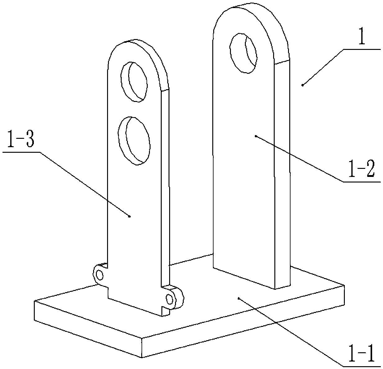
[0029] Combine below Figure 1-9 This embodiment will be described. This embodiment will further describe Embodiment 1. The drive shaft frame 1 includes a base 1-1, an output shaft frame 1-2, and an input shaft frame 1-3. The output shaft frame 1-2 and The input shaft frame 1-3 is fixedly connected to the base 1-1, the output shaft assembly 2 is rotatably connected to the output shaft frame 1-2, and the input shaft 3 is rotatably connected to the input shaft frame 1-3. The output shaft assembly 2 is coaxial with the input shaft 3 .


PUM


Abstract

The invention relates to the technical field of new-energy automobiles, in particular to a new-energy automobile device. The new-energy automobile device comprises a drive shaft bracket, an output shaft component, an input shaft, an intermediate gear frame, an intermediate gear, a sun gear and elastic telescopic shafts. The output shaft component is rotationally connected to one end of the drive shaft bracket, the input shaft is rotationally connected to the other end of the drive shaft bracket, the intermediate gear frame is rotationally connected to the input shaft, one end of each elastic telescopic shaft is hinged to the eccentric position of the intermediate gear frame, the other end of each elastic telescopic shaft is hinged to the drive shaft bracket, the sun gear is fixedly connected to the input shaft, the intermediate gear is rotationally connected to the intermediate gear frame and engaged with the sun gear, and the intermediate gear is in engaged connection with the outputshaft component through a gear. When the drive force of an automobile motor suddenly changes, drive force is in cushioned transition, coil current overload losses or damages of the automobile motor can be avoided, and stable drive force transmission is achieved.

Description

technical field [0001] The invention relates to the technical field of new energy vehicles, more specifically, a new energy vehicle equipment. Background technique [0002] For example, a drive device for a new energy vehicle with the patent application number CN201310112569.2 includes a main drive device, the power output shaft of the first motor / generator of the main drive device is connected to the power transmission of the wheel axle transmission mechanism, and its : It also includes a power-increasing energy-saving driving device, and the power-increasing energy-saving driving device includes: a flywheel; the flywheel is matched with the flywheel brake correspondingly, and the flywheel is connected to the power transmission of the flywheel shaft; a power coupling transmission assembly; the power The coupling transmission assembly includes a ring gear, a planetary gear, a planet carrier and a sun gear, the ring gear is connected to the flywheel shaft for power transmissi...

Claims


Application Information

Patent Timeline
Patent Type & Authority Applications(China)
IPC IPC(8): B60K17/04B60K17/08B60K25/06
CPCB60K17/04B60K17/08B60K25/06
Inventor 王淑莲
Owner 江苏贝肯盛创新能源科技有限公司
Why Eureka
Try Eureka