Tight clamping control device of air cylinder over-positioning

A control device and over-positioning technology, applied in the direction of conveyor control devices, transportation and packaging, conveyor objects, etc., can solve problems affecting the accuracy of equipment operation, inaccurate rocker arm positioning, and unsatisfactory structures, etc., to achieve extended use Long life, solution to clamping deviation, simple structure

Pending Publication Date: 2018-09-18
上海苏腾机械设备有限公司
View PDF0 Cites 4 Cited by
  • Summary
  • Abstract
  • Description
  • Claims
  • Application Information

AI Technical Summary

Problems solved by technology

The schematic diagram of the existing clamp structure and crank connecting rod principle is as follows: figure 2 , 3 As shown, the cylinder is directly connected to and controls the rocker arm. The structure of the rocker arm is C-shaped, and the structure is not ideal. There is a certain deviation in the shrinkage of the cylinder itself, which will easily lead to inaccurate positioning of the rocker arm, clamping deviation, and affect the accuracy of equipment operation. , causing the product to be inaccurately docked or unstable after docking

Method used


Image

  • Tight clamping control device of air cylinder over-positioning
  • Tight clamping control device of air cylinder over-positioning
  • Tight clamping control device of air cylinder over-positioning

Examples


Embodiment

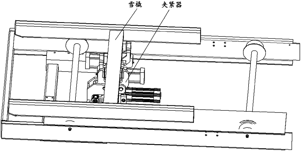
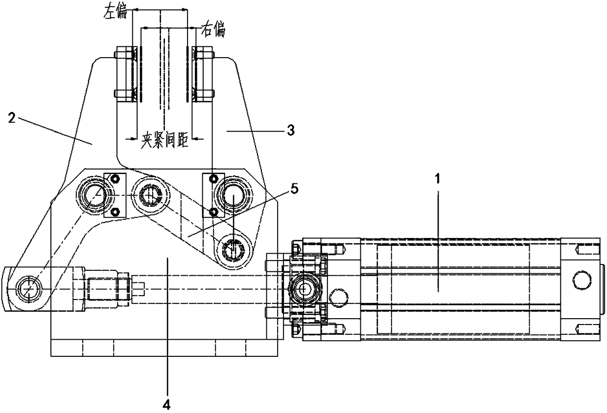
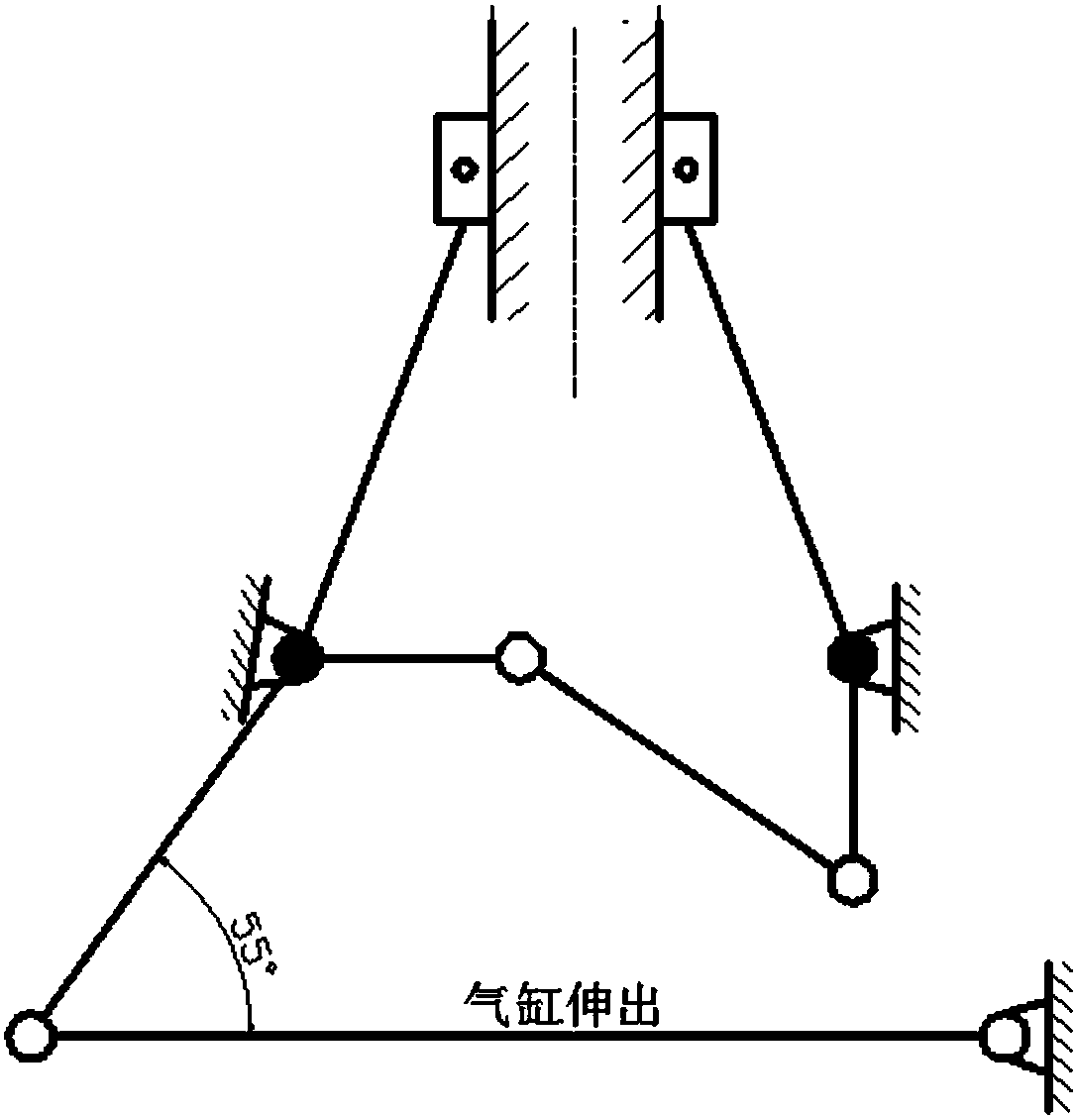
[0040] A cylinder over-positioning clamping control device, refer to the attached Figure 4-11 , comprising a base plate 7, a cylinder 1 located on one side of the base plate 7, and a clamping mechanism located on the upper part of the base plate 7, the clamping mechanism includes a rocker arm 2 and a cantilever arm 3, and the upper ends of the rocker arm 2 and the cantilever arm 3 are provided with a clamp assembly 6 , the upper part of the base plate 7 is vertically provided with two support plates, the rocker arm 2 and the cantilever 3 are arranged on the two support plates 4 through the shaft and the bearing assembly and are in the middle of the two support plates 4, and the rocker arm 2 and the cantilever 3 pass through a single lug The connecting rod 5 is hinged, and a sliding connection mechanism is provided between the output shaft of the cylinder 1 and the rocker arm 2. The sliding connection mechanism includes a double ear connecting rod 8, a pair of balance bearings ...


PUM


Abstract

The invention relates to a tight clamping control device of an air cylinder over-positioning. The device comprises a bottom plate, an air cylinder and a tight clamping mechanism, wherein the tight clamping mechanism comprises a rocker arm and a cantilever, two supporting plates are vertically arranged on the upper portion of the bottom plate, the rocker arm and the cantilever are arranged on thetwo supporting plates through a shaft and a bearing assembly and are located in the middle of the two supporting plates, and the rocker arm and the cantilever are hinged through a single-lug connecting rod; a sliding connecting mechanism is arranged between an output shaft of the air cylinder and the rocker arm, and the sliding connecting mechanism comprises a double-lug connecting rod, a pair ofbalancing bearings and a pair of parallel rails arranged on the bottom plate, wherein the upper end of the double-lug connecting rod is hinged to the rocker arm, the lower end of the double-lug connecting rod is connected with the tail end of an output shaft of the air cylinder, and the balancing bearings are arranged on the two sides of the lower end of the double-lug connecting rod through the shaft to move horizontally along the rails; when the air cylinder extends out, the tight clamping mechanism is clamped; and when the air cylinder retracts, the tight clamping mechanism is loosened. Compared with the prior art, the double-lug connecting rod and the rocker arm are connected by adopting the air cylinder to form right-angle locking to control the positioning of a tight clamping block,so that the defects of tight clamping deviation, unfirm tight clamping and the like are overcome.

Description

technical field [0001] The invention relates to a pneumatic clamping control device, in particular to a cylinder over-positioning clamping control device. Background technique [0002] In the conveying equipment production line for the production and assembly of automobile products, the sled (the conveying equipment carrying automobile products, similar to skis, generally called sled in the industry) is controlled to stop smoothly during operation according to the process or assembly needs, and the brake of the sled is usually used Cylinder clamping control device (clamp) braking, such as figure 1 shown. The schematic diagram of the existing clamp structure and crank connecting rod principle is as follows: figure 2 , 3 As shown, the cylinder is directly connected to and controls the rocker arm. The structure of the rocker arm is C-shaped, and the structure is not ideal. There is a certain deviation in the shrinkage of the cylinder itself, which will easily lead to inaccu...

Claims


Application Information

Patent Timeline
Patent Type & Authority Applications(China)
IPC IPC(8): B65G35/00B65G43/00
CPCB65G35/00B65G43/00B65G2203/042
Inventor 宋旭东
Owner 上海苏腾机械设备有限公司
Why Eureka
Try Eureka