Motion hopper automatic identification and positioning method based on depth visual information

A deep vision and automatic recognition technology, applied in image data processing, image enhancement, instruments, etc., can solve problems such as the inapplicability of research objects, and achieve the effect of fast calculation speed, good effect and high degree of automation

Inactive Publication Date: 2018-09-18
SHANGHAI UNIV
View PDF13 Cites 17 Cited by
  • Summary
  • Abstract
  • Description
  • Claims
  • Application Information

AI Technical Summary

Problems solved by technology

The above method solves the problem of moving object recognition from the perspective of two-dimensional vision, and this type of conventional method is not applicable to the research object of the present invention

Method used


Image

  • Motion hopper automatic identification and positioning method based on depth visual information
  • Motion hopper automatic identification and positioning method based on depth visual information
  • Motion hopper automatic identification and positioning method based on depth visual information

Examples


Embodiment Construction

[0023] The present invention is described in detail below in conjunction with accompanying drawing and specific embodiment, and present embodiment is carried out under the premise of technical solution of the present invention, has provided detailed implementation mode and process, but protection scope of the present invention is not limited to following Example.

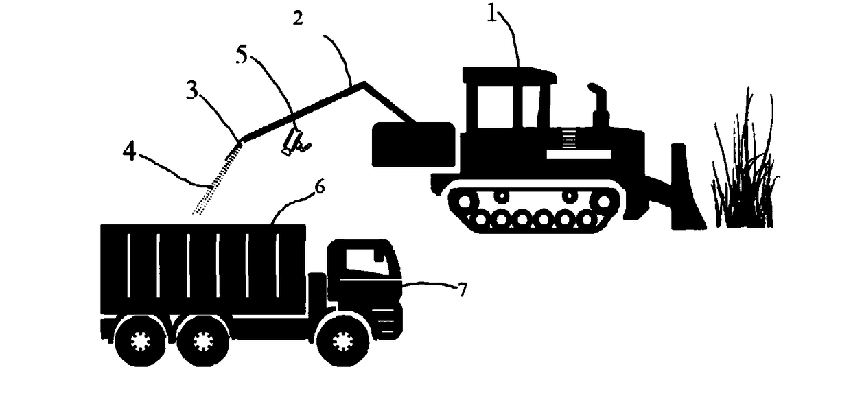
[0024] Such as figure 1 As shown, 1 in the figure is the harvesting vehicle of the green feeding machine, 2 is the mechanical arm, 3 is the nozzle, 4 is the green feed, 5 is the camera, 6 is the bucket, and 7 is the trailer. The throwing device consisting of arms is thrown out and received by the trailer's body. The key to using computer to replace manual material automatic filling system is to determine the relative position between the robot arm nozzle of the green feeding machine and the trailer body. After the relative positions of the two are determined, the drop point of the green feed is determined accordin...


PUM


Abstract

The invention relates to a motion hopper automatic identification and positioning method based on depth visual sense information; the method comprises the following steps: S1, parsing a rotation matrix R and a translation matrix t between a camera coordinate system and a world coordinate system; S2, reading a frame of depth image that contains depth visual sense information from a camera, and reading a frame of point cloud data; S3, downsampling the point cloud data; 4, converting the point cloud data under the camera coordinate system into the point cloud data under the world coordinate system; S5, carrying out threshold process for the converted point cloud data, keeping a lattice of an approximate height area to which the hopper is located, carrying out dimension reduction process for the point cloud after threshold processing, and projecting same to a two dimensional plane; S6, using an image processing technology to carry out a fitting process for the point cloud after dimension reduction, thus obtaining a hopper edge straight line, and calculating an angle point of the same. The method can automatically identify the outer profile of the hopper of a trailer, can obtain the angle and position of the hopper with respect to a machinery arm nozzle, and can automatically control the nozzle height and angle to make corresponding adjustments.

Description

technical field [0001] The invention relates to the fields of machine vision and agricultural automation, in particular to a method for automatically identifying and locating a moving agricultural trailer body based on depth vision information. Background technique [0002] The green forage machine is a commonly used agricultural harvesting machine, which is mainly used to harvest low green forage crops such as green grass, oats, beet stems and leaves. The green feeding machine is generally composed of the front header, the body feeding device and the chopping and throwing device. The front header is a rotary chopper equipped with multiple throwing knives for high-speed harvesting of crops. The fuselage collects and chops the crops, and then is thrown out by the throwing device. The main component of the throwing device is a two-degree-of-freedom mechanical arm structure with controllable angle and height. The materials thrown out by the green feeding machine are taken ove...

Claims


Application Information

Patent Timeline
Patent Type & Authority Applications(China)
IPC IPC(8): G06T7/00G06T7/73A01D43/08
CPCA01D43/085G06T7/0004G06T7/73G06T2207/10028G06T2207/20164G06T2207/30108
Inventor 何创新苗中华刘成良陈苏跃
Owner SHANGHAI UNIV
Why Eureka
Try Eureka