Dye stirring apparatus of fabric printing and dyeing equipment

A technology of printing and dyeing equipment and stirring device, which is applied in the field of fabric printing and dyeing, can solve the problems of dye deposition at the bottom of a stirring tank, adding a stirring shaft, and inability to stir, etc.

Inactive Publication Date: 2018-09-21
长兴瑞韬纺织科技有限公司
View PDF1 Cites 3 Cited by
  • Summary
  • Abstract
  • Description
  • Claims
  • Application Information

AI Technical Summary

Problems solved by technology

[0003] The patent document with the notification number CN205965644U discloses a dye stirring device, including a stirring barrel, a stirring shaft located inside the stirring barrel, and a power motor arranged on the stirring shaft to drive the stirring shaft to rotate. There is a fixed frame on the top, and a through hole for the power motor to pass through is arranged on the fixed frame. A scroll spring is provided between the through hole and the power motor to make the stirring shaft realize the circumferential rotation. The fixed frame and the power motor are connected with a The limiting member restricts the axial movement of the power motor. This solution increases the stability of the stirring shaft during the stirring process on the premise of ensuring that the stirring shaft can be adjusted, so that the water flow and the dye can be mixed better. The dye due to stirring In order to stir the solid fuel block in the chamber, when the stirring is not complete, there must be a part of the dye deposited on the bottom of the stirring tank, which cannot be completely stirred. Therefore, it needs to be improved

Method used


Image

  • Dye stirring apparatus of fabric printing and dyeing equipment
  • Dye stirring apparatus of fabric printing and dyeing equipment
  • Dye stirring apparatus of fabric printing and dyeing equipment

Examples


Embodiment Construction

[0022] The following will clearly and completely describe the technical solutions in the embodiments of the present invention with reference to the accompanying drawings in the embodiments of the present invention. Obviously, the described embodiments are only some, not all, embodiments of the present invention.

[0023] In describing the present invention, it should be understood that the terms "center", "longitudinal", "transverse", "length", "width", "thickness", "upper", "lower", "front", " Orientation indicated by rear, left, right, vertical, horizontal, top, bottom, inside, outside, clockwise, counterclockwise, etc. The positional relationship is based on the orientation or positional relationship shown in the drawings, and is only for the convenience of describing the present invention and simplifying the description, rather than indicating or implying that the referred device or element must have a specific orientation, be constructed and operated in a specific orientat...


PUM


Abstract

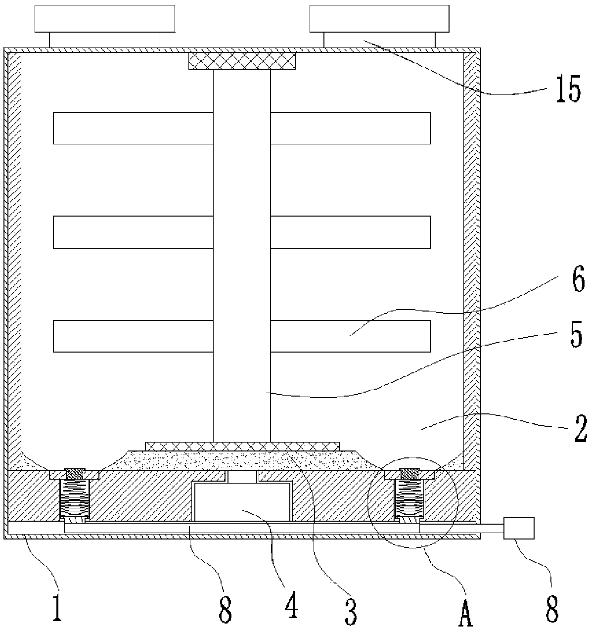
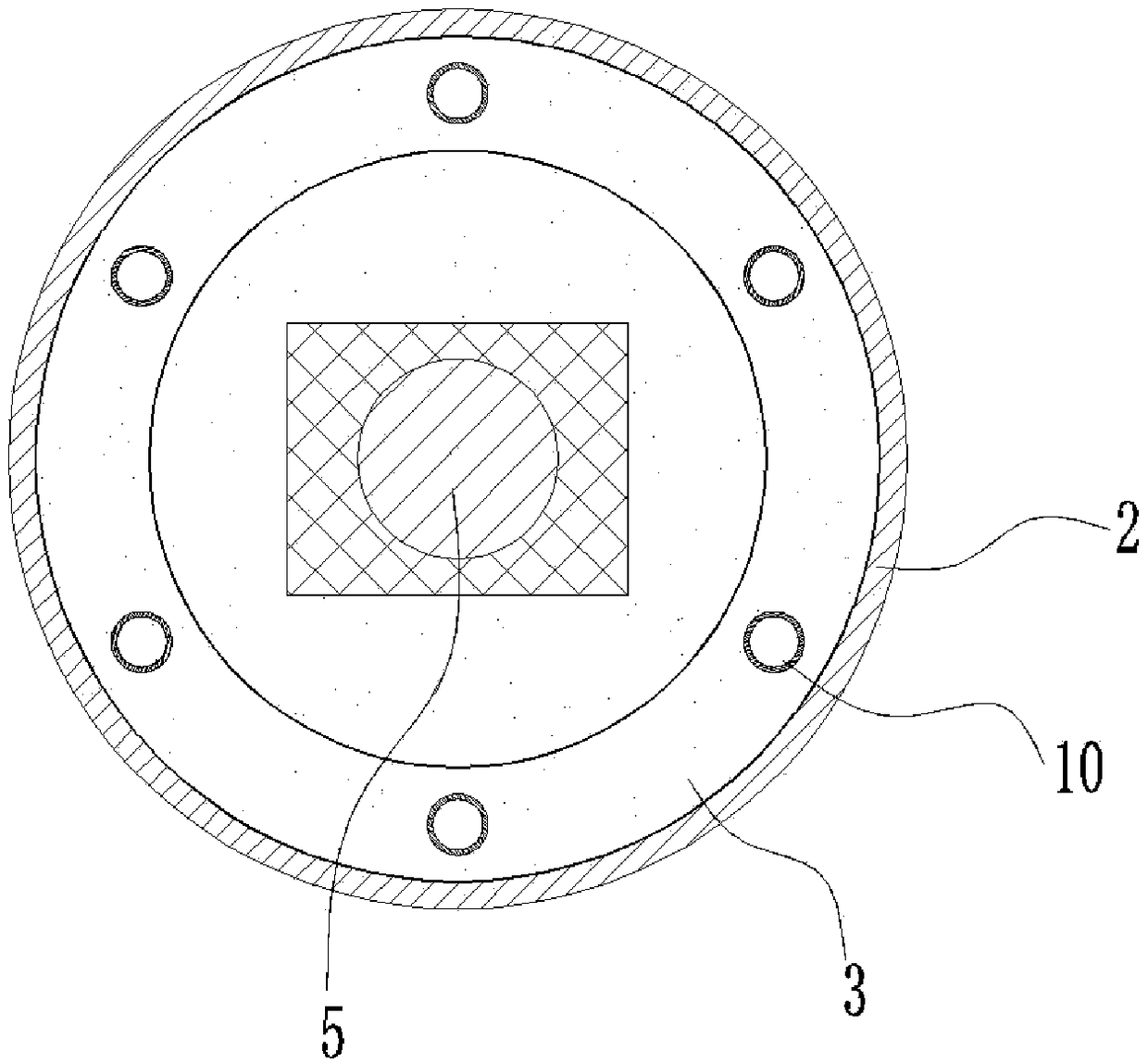
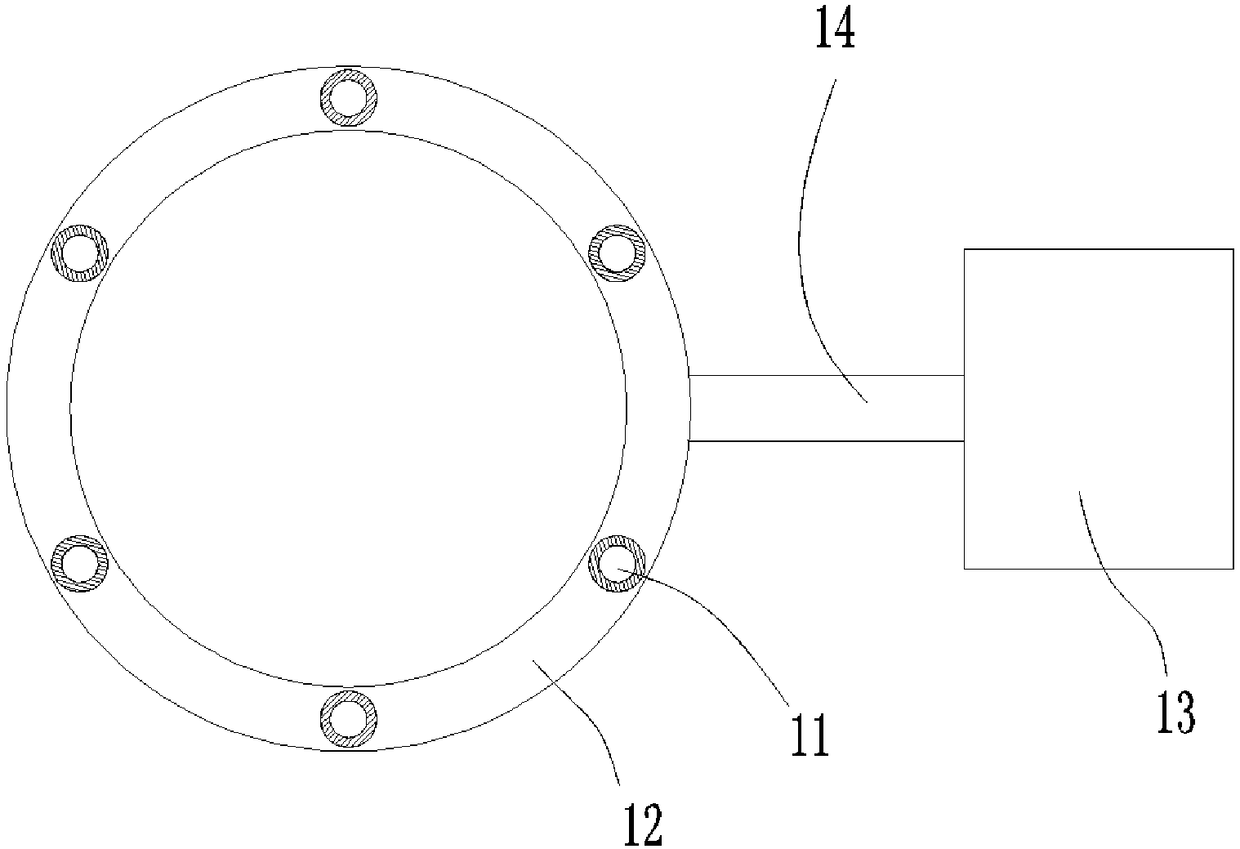
The invention discloses a dye stirring apparatus of fabric printing and dyeing equipment. The dye stirring apparatus comprises a housing, inside which a stirring chamber is arranged. A base plate is arranged on the inner wall of the bottom of the stirring chamber. A motor is arranged on the bottom of the stirring chamber. 4-6 vertical cylinders are inserted in the bottom of the stirring chamber. Apiston is arranged inside each cylinder. A spring is installed on the top of each piston. One end of each spring, far from the piston, is fixed on the inner wall of the top of the cylinder. The top of each cylinder is in threaded connection with a water outlet interface, and the bottom of the cylinder is in threaded connection with an air inlet interface. The bottom of the stirring chamber is provided with a connecting pipe. The top of the housing is equipped with a feed inlet. According to the invention, the stirring effect of dye preparation can be enhanced, and the content of dyes which are not completely stirred but deposited at the bottom during stirring can be reduced as much as possible. By the dye stirring apparatus, working efficiency is improved.

Description

technical field [0001] The invention relates to the technical field of fabric printing and dyeing, in particular to a dye stirring device of fabric fabric printing and dyeing equipment. Background technique [0002] In the textile industry, during the preparation of dyes, it is generally necessary to carry out the stirring operation of dyes. When the dyes are just bought, they are block-shaped dye raw materials. These dye raw materials need to be stirred by adding water through a stirring device, so that Forms a dye liquor that can be used to dye the yarn. [0003] The patent document with the notification number CN205965644U discloses a dye stirring device, including a stirring barrel, a stirring shaft located inside the stirring barrel, and a power motor arranged on the stirring shaft to drive the stirring shaft to rotate. There is a fixed frame on the top, and a through hole for the power motor to pass through is arranged on the fixed frame. A scroll spring is provided b...

Claims


Application Information

Patent Timeline
Patent Type & Authority Applications(China)
IPC IPC(8): B01F13/10B01F15/00
CPCB01F33/822B01F35/3203B01F35/3204B01F2101/30
Inventor 杭鹏程李岩郭小冰
Owner 长兴瑞韬纺织科技有限公司
Why Eureka
Try Eureka