Mixed fluid stirring mechanism and tubular reactor
A technology for tubular reactors and stirring mechanisms, applied in mixers, chemical/physical/physicochemical stationary reactors, mixers with rotating stirring devices, etc. The purpose of mixing different materials and other issues to achieve the effect of improving space utilization, small total volume, and reducing side reactions
- Summary
- Abstract
- Description
- Claims
- Application Information
AI Technical Summary
Problems solved by technology
Method used
Image

Examples
Embodiment approach
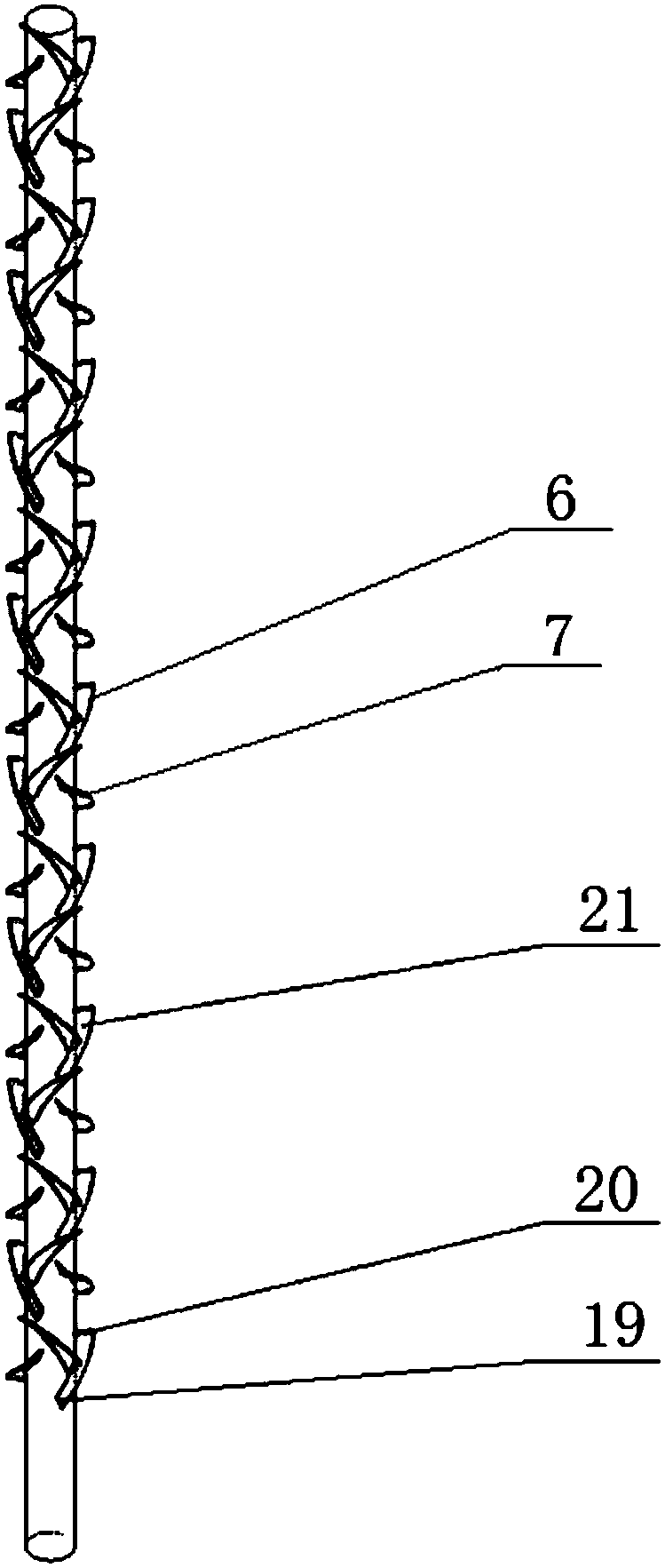
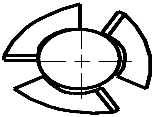
[0080] In the first embodiment, with the same helix angle and the number of paddles, the area of the forward stirring structure 6 is larger than the area of the reverse stirring structure 7 .
[0081] As a preferred embodiment of the first embodiment, the height of the forward stirring structure 6 and the reverse stirring structure 7 is the same, and the width of the forward stirring structure 6 is greater than the width of the push-down stirring structure 7, preferably the width of the forward stirring structure 6 1.01 to 2 times the width of the push-down stirring 7 structure;
[0082] As another preferred embodiment of the first embodiment, the width of the forward stirring structure 6 and the reverse stirring structure 7 are the same, and the height of the forward stirring structure 6 is greater than that of the reverse stirring structure 7;
[0083] As another preferred embodiment of the first embodiment, the forward stirring structure 6 and the reverse stirring struc...
PUM
 Abstract
Description
Claims
Application Information
 - Generate Ideas
- Intellectual Property
- Life Sciences
- Materials
- Tech Scout
- Unparalleled Data Quality
- Higher Quality Content
- 60% Fewer Hallucinations
Browse by: Latest US Patents, China's latest patents, Technical Efficacy Thesaurus, Application Domain, Technology Topic, Popular Technical Reports.
© 2025 PatSnap. All rights reserved.Legal|Privacy policy|Modern Slavery Act Transparency Statement|Sitemap|About US| Contact US: help@patsnap.com