Synchronous rotation pressure-bearing type forming mold structure of magnetic field forming press

A molding die and synchronous rotation technology, applied in the field of synchronous rotary pressure-bearing molding die structure, to achieve the effects of good pressing effect, uniform density distribution and low rejection rate

Pending Publication Date: 2018-09-21
BAIQIDA INTELLIGENT TECH NINGBO CO LTD
View PDF6 Cites 2 Cited by
  • Summary
  • Abstract
  • Description
  • Claims
  • Application Information

AI Technical Summary

Problems solved by technology

[0004] In view of the deficiencies in the prior art above, the purpose of the present invention is to provide a synchronous rotating pressure-bearing forming mold structure of a magnetic field forming press; by adding a rotating mechanism, when adding NdFeB powder into the forming mold, the lower The mold, forming mold and mandrel can be rotated, so that the density distribution of the NdFeB powder in the cavity of the forming mold is uniform, and the product is not easy to produce defects during molding and pressing, and the magnetic distribution of the pressed radiation ring is uniform

Method used


Image

  • Synchronous rotation pressure-bearing type forming mold structure of magnetic field forming press
  • Synchronous rotation pressure-bearing type forming mold structure of magnetic field forming press
  • Synchronous rotation pressure-bearing type forming mold structure of magnetic field forming press

Examples


Embodiment Construction

[0019] The following descriptions are only preferred embodiments of the present invention, and therefore do not limit the protection scope of the present invention.

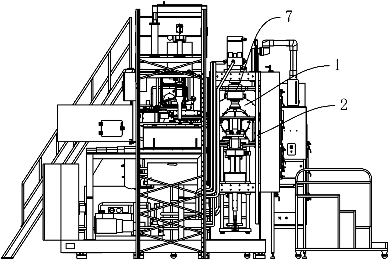
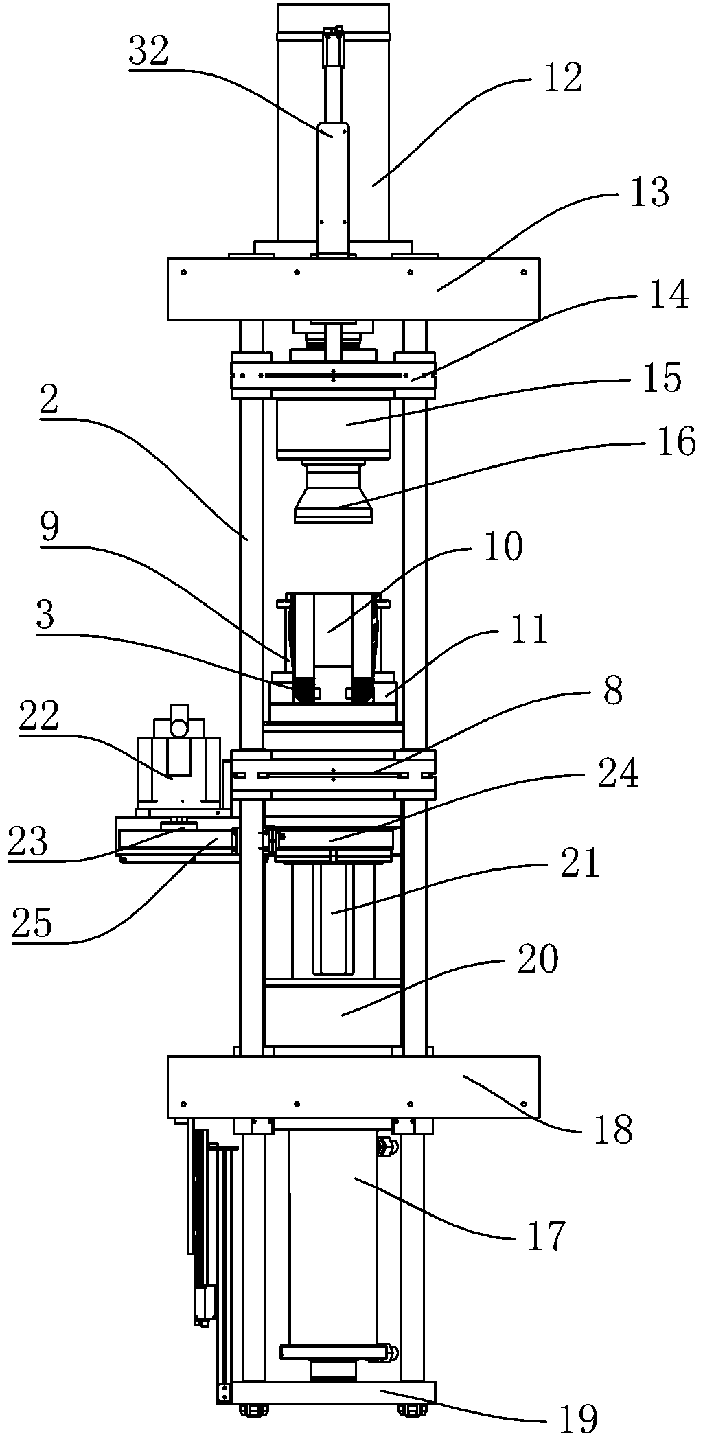
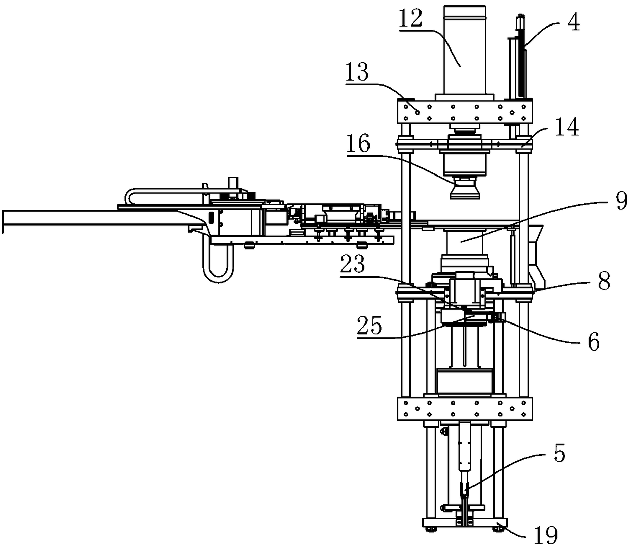
[0020] Examples, see Figure 1 to Figure 3 Shown: a synchronous rotating pressure-bearing forming mold structure of a magnetic field forming press, including a guide column 2, a middle guide plate 8, a forming mold 9, a mold frame 11, an upper punch, a lower punch, and a magnetic field coil 1, and a middle guide plate 8 is installed on the guide column 2, the mold base 11 is rotatably installed on the middle guide plate 8, the forming mold 9 is installed on the mold base 11, and a mandrel 10 is arranged inside the forming mold 9, and the mandrel 10 is installed on the mold base 11 , the upper punch and the lower punch are located at the upper and lower ends of the forming die 9 respectively, and the magnetic field coil 1 is located at the side of the forming die 9 . The upper punch includes an upper cylinder 12,...


PUM


Abstract

The invention discloses a synchronous rotation pressure-bearing type forming mold structure of a magnetic field forming press. A forming device comprises guide columns, a middle guide plate, a formingmold, a mold frame, an upper punch, a lower punch and a magnetic field coil; a core rod is arranged in the forming mold, the upper punch and the lower punch are located at the upper end and the lowerend of the forming mold respectively, and the magnetic field coil is located beside the forming mold; the upper punch comprises an upper cylinder, a top plate, an upper guide plate and an upper mold;and the lower punch comprises a lower cylinder, a lower guide plate, a lower mold continuous base and a lower mold fixing base. According to the synchronous rotation pressure-bearing type forming mold structure, a rotating mechanism is further arranged on the bottom plate, and the rotating mechanism is additionally arranged, so that when the neodymium iron boron powder is added into the forming mold, the lower mold, the forming mold and the core rod can rotate, the density distribution of the neodymium-iron-boron powder in the mold cavity of the forming mold is uniform, and a product is not prone to generating defects when being formed and pressed.

Description

technical field [0001] The invention relates to the technical field of metallurgical powder forming presses, in particular to a synchronous rotating pressure-bearing forming die structure of a magnetic field forming press. Background technique [0002] The magnetic field molding press mainly includes a sealed frame, which is equipped with a powder weighing device, a feeding device and a molding device. The NdFeB powder first enters the powder weighing device through the barrel, and the powder weighing device weighs the quantitative NdFeB powder. Then put it into the feeding device, and finally push it to the molding device by the feeding device, and put the NdFeB powder into the molding mold. [0003] The powder filling device of the existing magnetic field forming press has a uniform density distribution of the powder filled into the forming mold. If the density distribution of the powder filled into the cavity of the forming mold is not uniform, the product is prone to def...

Claims


Application Information

Patent Timeline
Patent Type & Authority Applications(China)
IPC IPC(8): B22F3/03
CPCB22F3/03B22F2999/00B22F2202/05
Inventor 王兴杰王晗权陈前锋周年生方辉鹤张雷
Owner BAIQIDA INTELLIGENT TECH NINGBO CO LTD
Why Eureka
Try Eureka