
Teflon fine tube cutting equipment

A Teflon thin tube and equipment technology, which is applied in shearing machine equipment, metal processing equipment, pipe shearing devices, etc., can solve the problems of poor incision quality, easy to cut oblique openings, and difficult to control, and achieve good incision quality. , Improve length accuracy, eliminate the effect of bending or flattening

Active Publication Date: 2018-09-21
新沂市新南环保产业技术研究院有限公司
View PDF9 Cites 2 Cited by
  • Summary
  • Abstract
  • Description
  • Claims
  • Application Information

AI Technical Summary

Problems solved by technology

Since the feeding is carried out by pressing the thin tube with the roller, the contact surface is small, and the pressure is adjusted manually, which is difficult to control. The thin tube is hard and easy to be bent or flattened, or slipped and deviated, and the cutting length and accuracy are difficult to guarantee. The quality of the cut is poor, it is easy to cut into oblique cuts, and the smaller the diameter of the thin tube, the more difficult it is to feed the material. This kind of material waste caused by bending or flattening the tube is huge

Method used


Image

  • Teflon fine tube cutting equipment
  • Teflon fine tube cutting equipment
  • Teflon fine tube cutting equipment

Examples


Embodiment approach 1

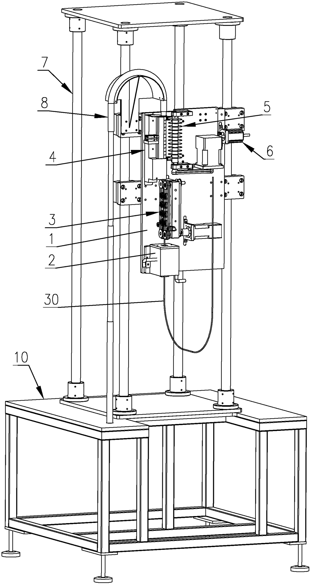
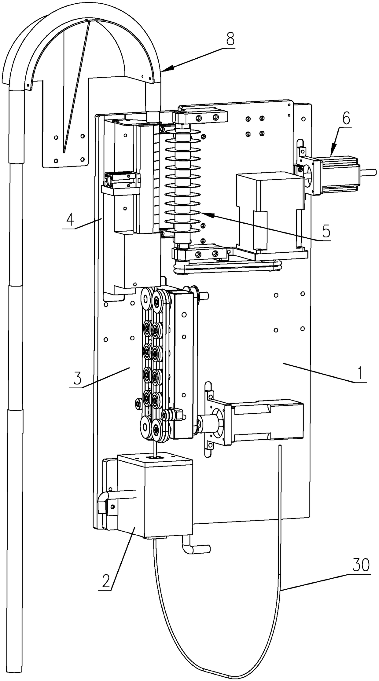
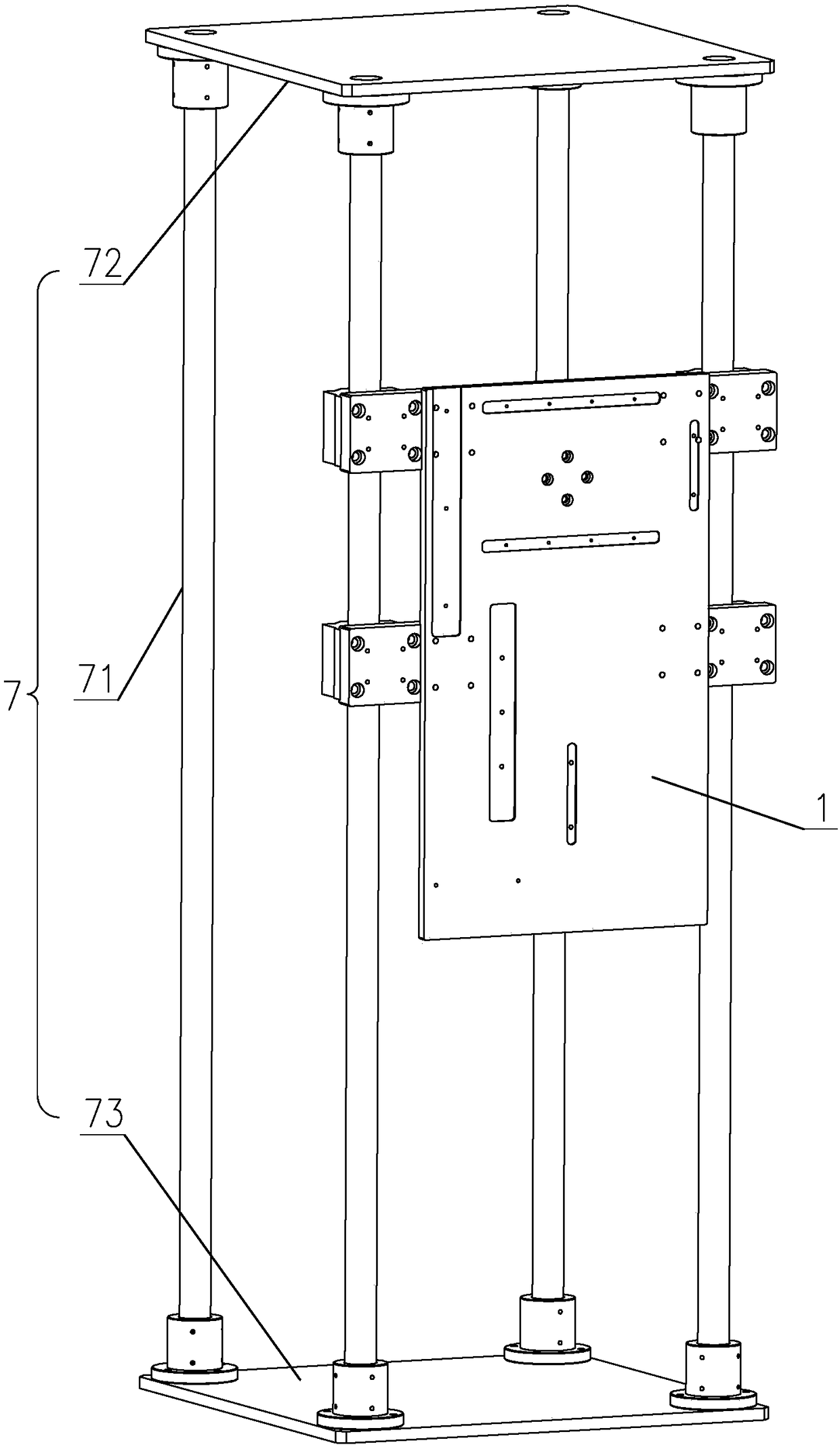
[0084] Such as figure 1 As shown, a Teflon thin tube cutting equipment includes a base 1, a cooling water tank 2, a conveying mechanism 3, a clamping mechanism 4, a cutting mechanism 5, a cutting driving mechanism 6, a supporting frame 7, an output mechanism 8, a machine Frame 10, collection box, and support frame 7 are provided with at least 2 support columns 71; Cooling water tank 2, conveying mechanism 3, clamping mechanism 4, cutting drive mechanism 6, output mechanism 8 are fixedly installed on base 1 respectively, and cutting mechanism 5 Fixedly installed on the cutting drive mechanism 6, the support frame 7 is fixedly installed on the frame 10, the base 1 is fixedly installed on the support column 71, the inlet of the output mechanism 8 communicates with the outlet of the clamping mechanism 4, and the collection box is placed on the frame 10; the Teflon thin tube 30 passes through the cooling water tank 2 and is inserted into the conveying mechanism 3, and the conveying...

Embodiment approach 2

[0092] Such as Figure 10 , Figure 11 As shown, the second embodiment is basically the same as the first embodiment, except that the clamping mechanism 4 is different. The clamping mechanism 4 of the second embodiment includes a main clamping block 44, and a plurality of secondary clamps are arranged on the front of the main clamping block 44 The holding block 45, the front of the main holding block 44 and the auxiliary holding block 45 are all provided with arc-shaped grooves 431 for clamping the Teflon thin tube 30, and the main holding block 44 side is provided with a breach 432 for cutting , the secondary clamping block 45 and the gap 432 are designed according to the length of the Teflon thin tube 30 after being cut, and a plurality of them can be evenly designed, and the second embodiment of the present invention is designed to be 12; the main clamping block 44 passes through the main clamping The mounting block 46 is fixedly mounted on the base 1 .

[0093] The prese...


PUM


Abstract

The invention provides teflon fine tube cutting equipment. The equipment comprises a base (1), a cooling water tank (2), a delivering mechanism (3), a clamping mechanism (4), a cutting mechanism (5),a cutting driving mechanism (6), a supporting framework (7), an output mechanism (8), a machine frame (10) and a collecting box; a teflon fine tube(30) penetrates through the cooling water tank (2) and is inserted into the delivering mechanism (3), the teflon fine tube (30) with a fixed length is delivered into the clamping mechanism (4) by the delivering mechanism (6) to be clamped, the cutting mechanism (5) is driven by the cutting driving mechanism (4) to cut the teflon fine tube (30) in the clamping mechanism, and the cut teflon fine tube (30) is output by the output mechanism (8) to the collecting box. By means of the equipment, the length precision of tube cutting can be effectively improved, the incision quality is good, and the bending or crushing of piping materials can be reducedor even eliminated.

Description

[0001] This application is a divisional application. The application number of the original application is: 2017101686591, the application date is: 2017-03-21, and the name of the invention is: a Teflon thin tube cutting equipment and method. technical field [0002] The invention relates to the technical field of industrial machinery automation, in particular to a Teflon narrow tube cutting device. Background technique [0003] In the cutting operation of Teflon thin tubes, it is usually necessary to cut a variety of short tubes of specific lengths for one type of tube. smooth. [0004] At present, for cutting Teflon thin tubes of a specific length, the common way is to use rollers to feed the material, and then cut it with a blade. The method is to press a Teflon thin tube with a pair of rollers. The active roller rotates to apply frictional force to the thin tube, and feeds the material forward continuously. After passing through a specific mold, when the thin tube reach...

Claims


Application Information

Patent Timeline
Patent Type & Authority Applications(China)
IPC IPC(8): B23D21/00B23Q11/10
CPCB23D21/00B23Q11/10
Inventor 不公告发明人
Owner 新沂市新南环保产业技术研究院有限公司
Learn More