
Clamping device

A technology of clamping device and clamping plate, which is applied in the direction of shearing device, cutting tool for shearing machine, metal processing equipment, etc., can solve the problems of deformation of clamping plate, deformation of cutting blade, insufficient friction, etc., and achieve force Uniform and solve the effect of cutting disc deformation

Pending Publication Date: 2018-09-21
LANGFANG SHENGSEN ABRASIVES CO LTD
View PDF0 Cites 0 Cited by
  • Summary
  • Abstract
  • Description
  • Claims
  • Application Information

AI Technical Summary

Problems solved by technology

[0004] The purpose of the present invention is to provide a clamping device to solve the problem of insufficient friction caused by the small contact area between the clamping plate and the cutting piece in the prior art. Concave, when the clamping force is too large, the deformation of the clamping plate will cause the deformation of the cutting piece

Method used


Image

  • Clamping device
  • Clamping device
  • Clamping device

Examples


Embodiment Construction

[0031] In order to make the purpose, technical solution and advantages of the present invention clearer, the technical solution of the present invention will be described in detail below. Apparently, the described embodiments are only some of the embodiments of the present invention, but not all of them. Based on the embodiments of the present invention, all other implementations obtained by persons of ordinary skill in the art without making creative efforts fall within the protection scope of the present invention.

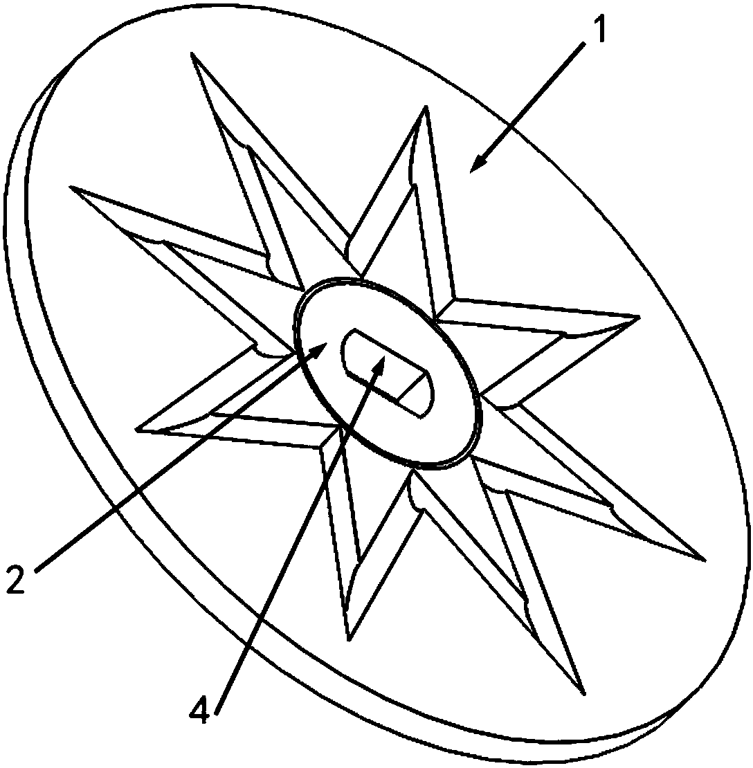
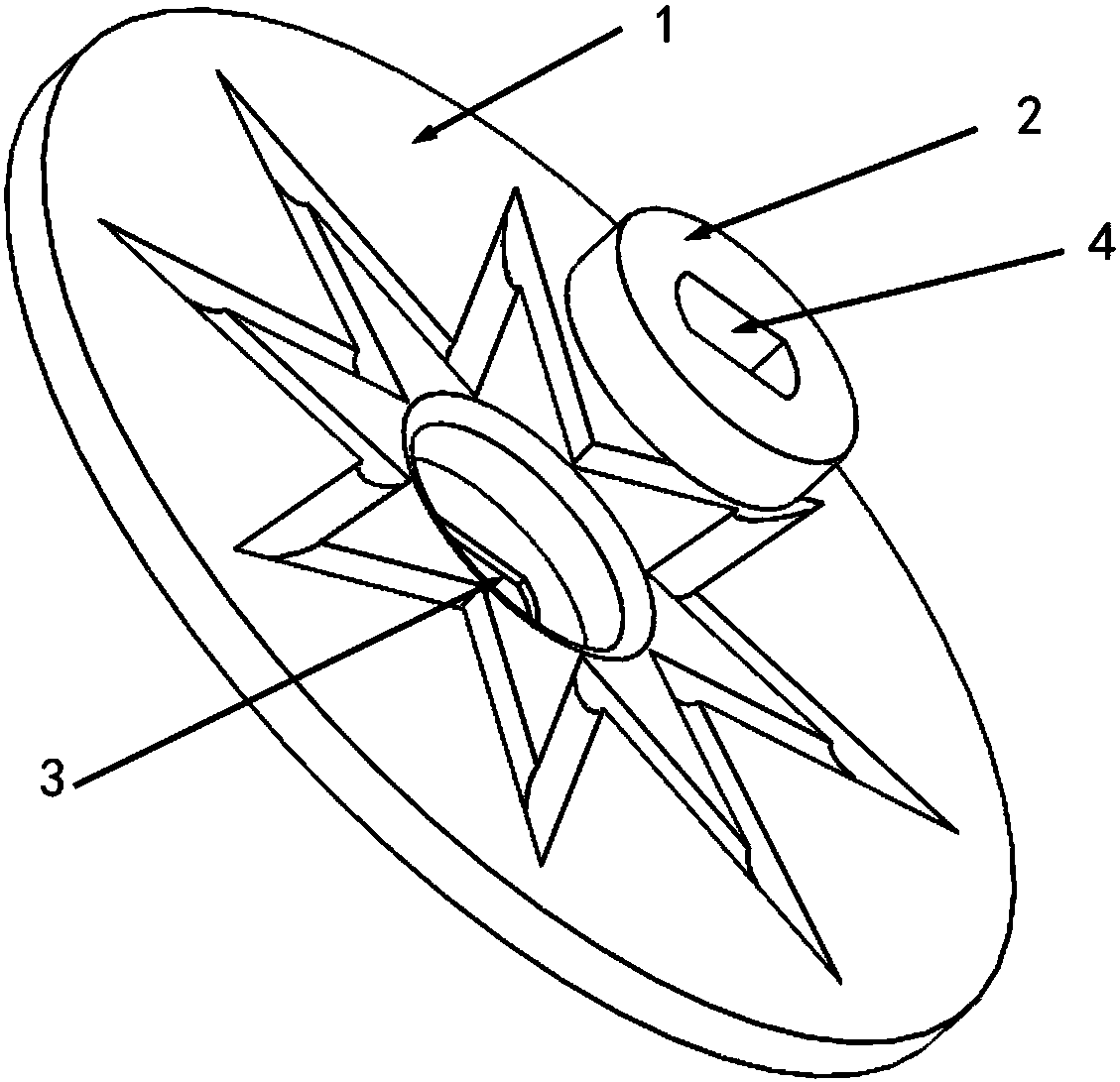
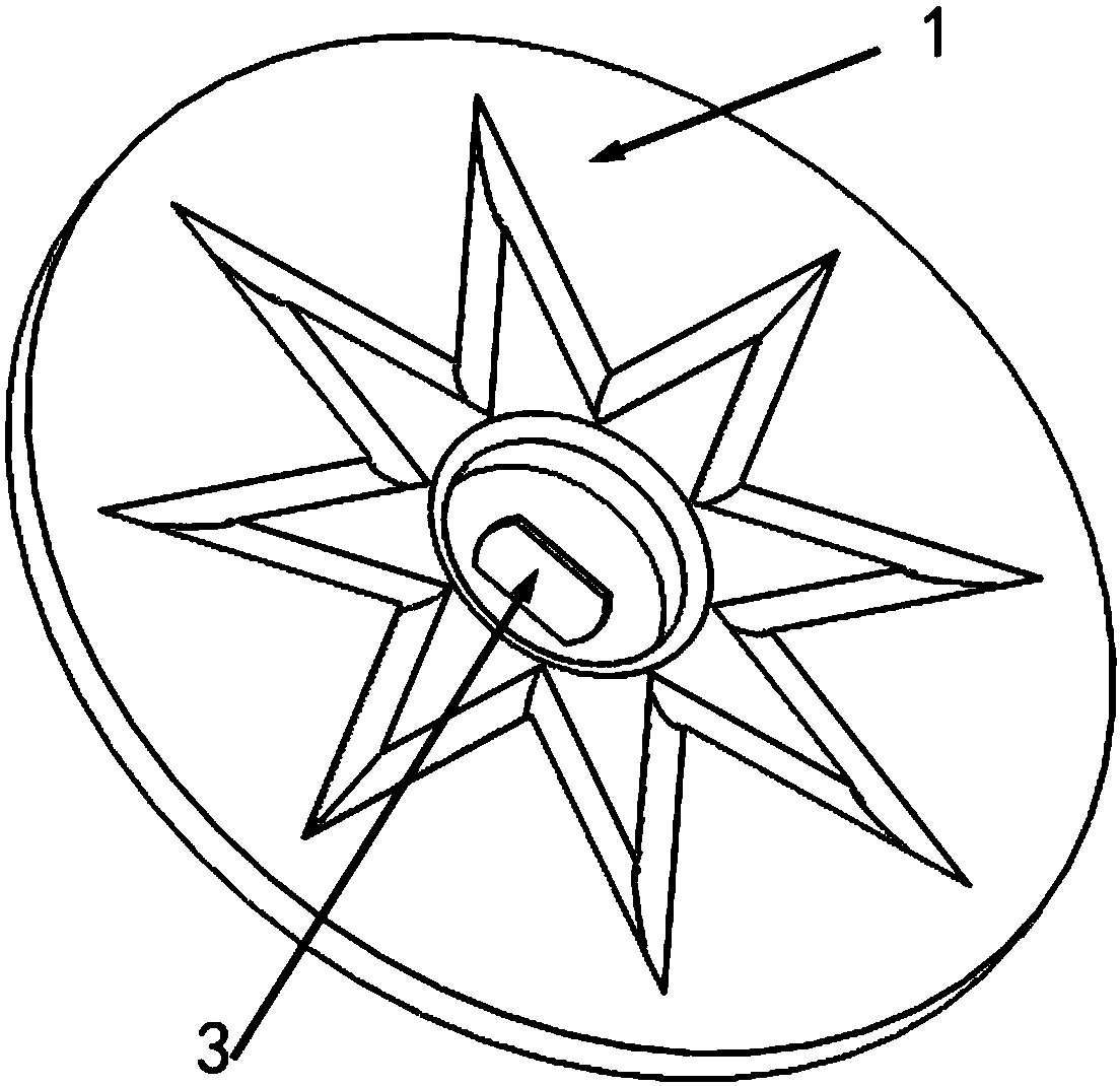
[0032] The invention provides a clamping device, see image 3 and Figure 4 The above-mentioned clamping device includes a clamping plate 1 and a gasket 2, the above-mentioned clamping plate 1 is disc-shaped, and is concave in the central area of ​​the side where the clamping plate 1 contacts the cutting piece, and the back of the concave part is opposite to the end surface of the clamping plate 1 Convex, the overall shape of the clamping plate 1 is similar to...


PUM

PropertyMeasurementUnit
Outer diameteraaaaaaaaaa
Thicknessaaaaaaaaaa

Abstract

The invention discloses a clamping device. The clamping device comprises a clamping plate and a gasket, wherein the clamping plate is in a circular disc shape with a concave center; the gasket is fixedly arranged in the concave center of the clamping plate; the end surface of the gasket at the side where the clamping device is in contact with a cutting piece is lower than the end surface of the clamping plate at the side; a first shaft hole is formed in the center of the clamping plate and is connected with a main shaft of a cutting machine; a second shaft hole is formed in the center of the gasket, and the shape and size of the second shaft hole are the same with the shape and size of the first shaft hole; the first shaft hole is aligned with the second shaft hole. The clamping device hasthe advantages that in the installation process, the clamping plate is firstly in contact with the cutting piece, the concave part of the clamping plate is deformed along with the continuous increasing of the clamping force, the gasket is in contact with the cutting piece, the contact area between the clamping device and the cutting piece is increased by the gasket, the condition of reduction ofcontact area due to tilting of surrounding areas of the clamping plate caused by large clamping force is avoided, and the problem of unenough friction force due to smaller contact area is solved; theinfluence to the use of the cutting piece because of deformation due to serious deformation of the clamping plate caused by the overlarge clamping force is also prevented.

Description

technical field [0001] The invention relates to the technical field of clamps, in particular to a clamping device. Background technique [0002] In the process of mechanical processing, cutting machines are often used for plate cutting. On large slice cutting machines, clamping plates similar to cymbals have been used, which are small in size and concave in the center. The small contact area results in insufficient friction, and the clamping plate and the cutting disc slip, resulting in excessive wear of the central part of the cutting disc, which is prone to safety accidents caused by rupture during use. [0003] In addition, if the installation force is too large during clamping, it will also cause excessive compression of the central concave part, resulting in deformation of the clamping plate, causing the circumference of the clamping plate to warp, further increasing the situation of small contact area and insufficient friction. When the deformation degree of the two-s...

Claims


Application Information

Patent Timeline
IPC IPC(8): B23D35/00
CPCB23D35/004
Inventor 许胜英
Owner LANGFANG SHENGSEN ABRASIVES CO LTD
Learn More