
Double-mold key hole-free stirring friction spot welding equipment

A friction stir and spot welding equipment technology, applied in welding equipment, non-electric welding equipment, metal processing equipment, etc., can solve the problems of inability to adjust the welding mode, less dense solder joints, limited working dimensions, etc., to reduce welding costs and energy consumption, improve welding quality and production efficiency, and reduce the effect of operating technology requirements

Inactive Publication Date: 2018-09-21
TAIYUAN UNIV OF TECH
View PDF8 Cites 4 Cited by
  • Summary
  • Abstract
  • Description
  • Claims
  • Application Information

AI Technical Summary

Problems solved by technology

The current keyhole friction stir spot welding equipment is mainly developed by the German GKSS Research Institute and Riftic Company. Its disadvantages are that the equipment is bulky, the control system is complicated, and the price is expensive. When the needle moves up, the sleeve and the probe need to be equipped with control systems to achieve the desired effect
[0005] Due to the large size of the current friction stir spot welding equipment, complex control, limited working dimensions, and less dense joints, the flexibility is poor when welding small areas or large complex structural parts, and the welding mode cannot be adjusted according to the actual situation. regulation, in which case the present invention applies

Method used


Image

  • Double-mold key hole-free stirring friction spot welding equipment
  • Double-mold key hole-free stirring friction spot welding equipment
  • Double-mold key hole-free stirring friction spot welding equipment

Examples


Embodiment Construction

[0020] Specific embodiments of the present invention will be described in detail below in conjunction with the accompanying drawings.

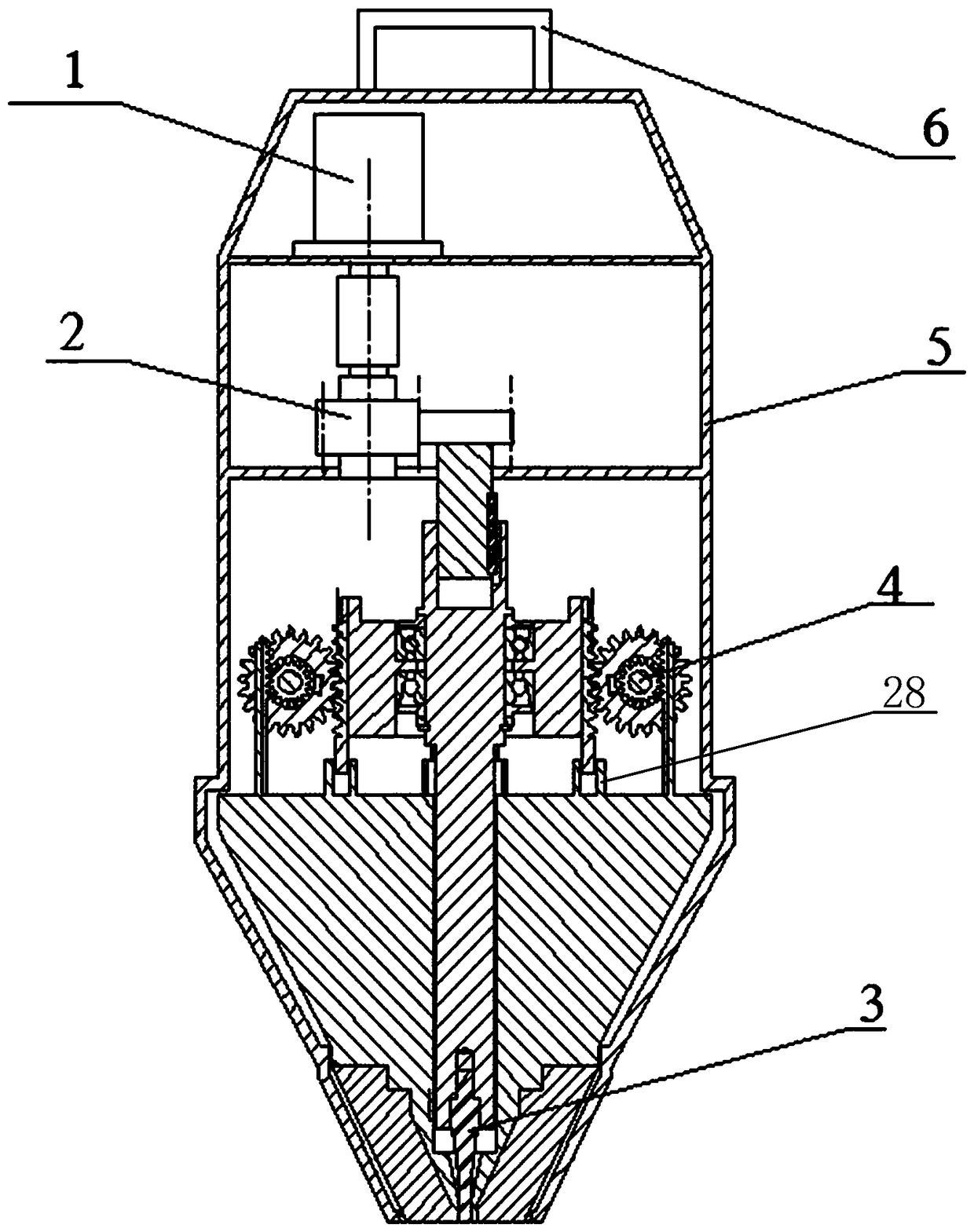
[0021] Such as figure 1 As shown, a dual-mode portable keyhole-less friction stir spot welding equipment with a linkage device mainly includes a power motor 1 , a transmission mechanism 2 , a welding mechanism 3 , a feeding mechanism 4 , an outer shell 5 , and a handle 6 .

[0022] The power motor 1 is preferably a three-phase AC speed-regulating brake motor.

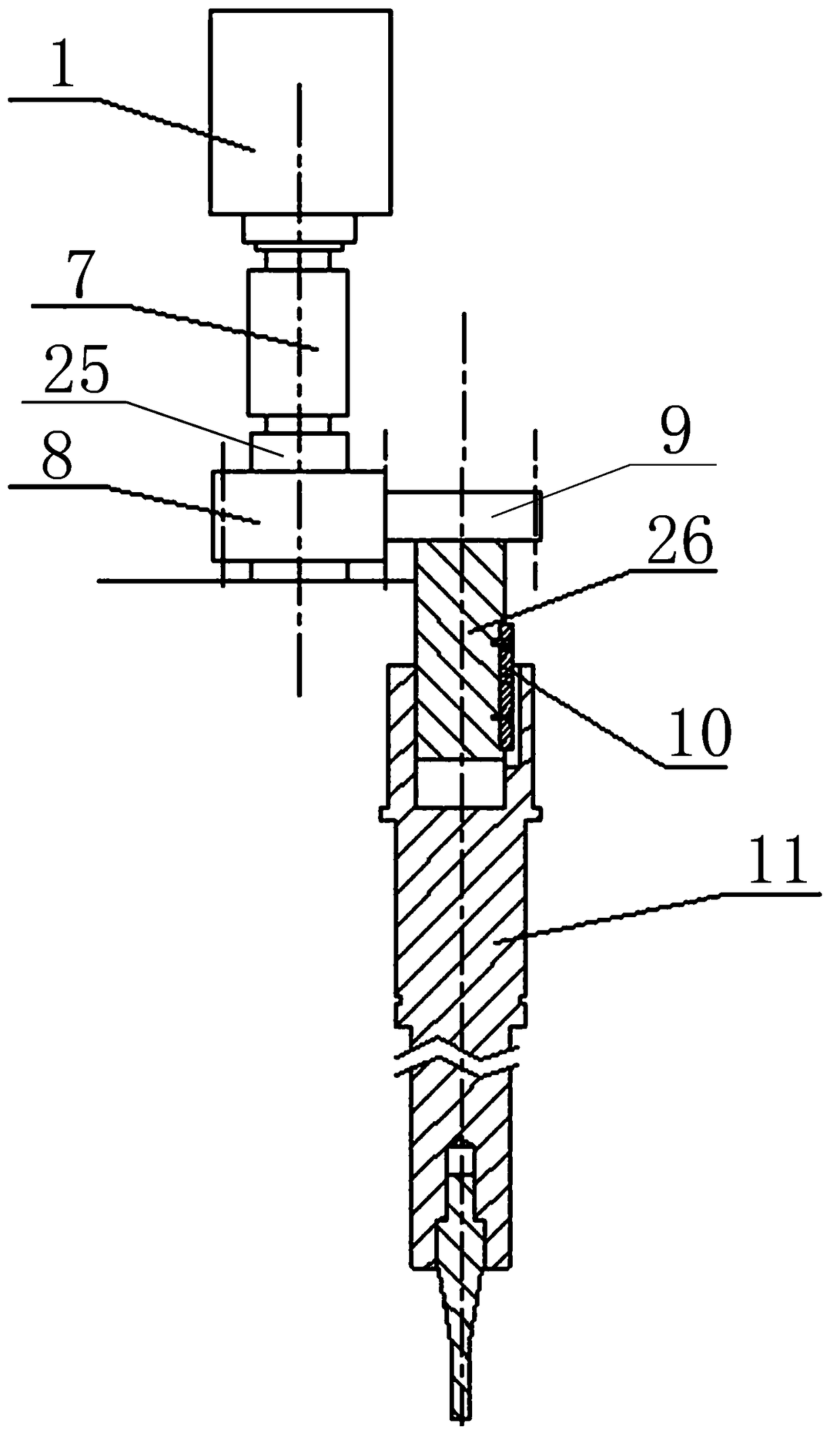
[0023] Such as figure 2 As shown, the transmission mechanism 2 is composed of a driving shaft 25, a driven shaft 26, a guide flat key 10 and a main shaft 11. The driving shaft 25 and the power motor 1 are connected through the sleeve coupling 7, and the driving shaft 25 is connected through the driving shaft gear on it. 8 meshes with the driven shaft gear 9 on the driven shaft 26, the driven shaft 26 and the main shaft 11 are connected through the guide flat key 10, and the main sha...


PUM


Abstract

The invention discloses double-mold key hole-free stirring friction spot welding equipment which comprises an outer shell (5), wherein a grip (6) is arranged on the top of the outer shell (5), and a power motor (1) is mounted in the outer shell (5); the power motor (1) is connected to a driving shaft (25) through a bush coupling (7), the driving shaft (25) is engaged to a driven shaft gear (9) ona driven shaft (26) through a driving shaft gear (8) on the driving shaft (25), and the driven shaft (26) is connected to the upper end of a main shaft (11) through a guide flat key (10); and a probe(12) is mounted at the lower end of the main shaft (11) through a thread. On the basis that key hole-free stirring friction spot welding is achieved, the size and weight of the equipment are reduced greatly, the demand on physical agility and skill of an operator is reduced, and meanwhile, the equipment has two welding modes which can be selected preferentially according to the welding condition,so that the equipment fully exerts a welding potential.

Description

technical field [0001] The invention belongs to the technical field of spot welding, in particular to a dual-mode keyhole-less friction stir spot welding equipment. Background technique [0002] In recent years, aluminum, magnesium and other lightweight alloys have been widely used in automobiles, locomotives, aerospace and other fields, and their connection technology has inevitably become the focus of research. At present, the more common aluminum alloy welding technology is resistance spot welding. The characteristics of resistance spot welding determine that it has the advantages of less consumables and lower product quality. However, the resistance spot welding of aluminum alloys, especially high-strength aluminum alloys, faces some difficulties: first, metallurgical defects such as pores and cracks are prone to appear in the joints, which significantly reduces the quality of the joints; second, the electrode life of aluminum alloy resistance spot welding is longer than...

Claims


Application Information

Patent Timeline
Patent Type & Authority Applications(China)
IPC IPC(8): B23K20/12B23K20/26
CPCB23K20/1265B23K20/26
Inventor 董鹏王鸿睿闫志峰王康翁卫平王清正王文先张红霞
Owner TAIYUAN UNIV OF TECH
Learn More