
Bamboo chip clamping device for drilling

A clamping device and technology for bamboo pieces, which are applied to drilling machines, wood processing appliances, manufacturing tools, etc., can solve the problem of reducing the drilling efficiency and hole position accuracy of the bamboo pieces by the drilling machine, reducing the hole position accuracy of the bamboo pieces and reducing the slippage of the bamboo pieces. It can solve problems such as opening and reducing the drilling efficiency of bamboo chips, so as to achieve the effects of improving work stability and service life, good clamping stability, and high positioning and installation efficiency.

Inactive Publication Date: 2018-09-21
安吉席丫丫竹木有限公司
View PDF7 Cites 2 Cited by
  • Summary
  • Abstract
  • Description
  • Claims
  • Application Information

AI Technical Summary

Problems solved by technology

This fixing method will not only cause a slight offset and inclination of the bamboo slices after being impacted by the drill bit, resulting in a decrease in the hole position accuracy of the bamboo slices and the hidden danger of the bamboo slices slipping away during drilling; Afterwards, the bamboo slices need to be repositioned. While reducing the drilling efficiency of the bamboo slices, the bamboo slices will cause errors in the installation position of the bamboo slices during the repeated positioning process, which reduces the drilling efficiency and the efficiency of the drilling machine for the bamboo slices. Hole position accuracy
Therefore, the existing methods of manually pressing and adjusting bamboo pieces have the problems of low positioning efficiency and poor clamping stability

Method used


Image

  • Bamboo chip clamping device for drilling
  • Bamboo chip clamping device for drilling
  • Bamboo chip clamping device for drilling

Examples


Embodiment Construction

[0015] The present invention will be further described below in conjunction with the accompanying drawings and embodiments, but not as a basis for limiting the present invention.

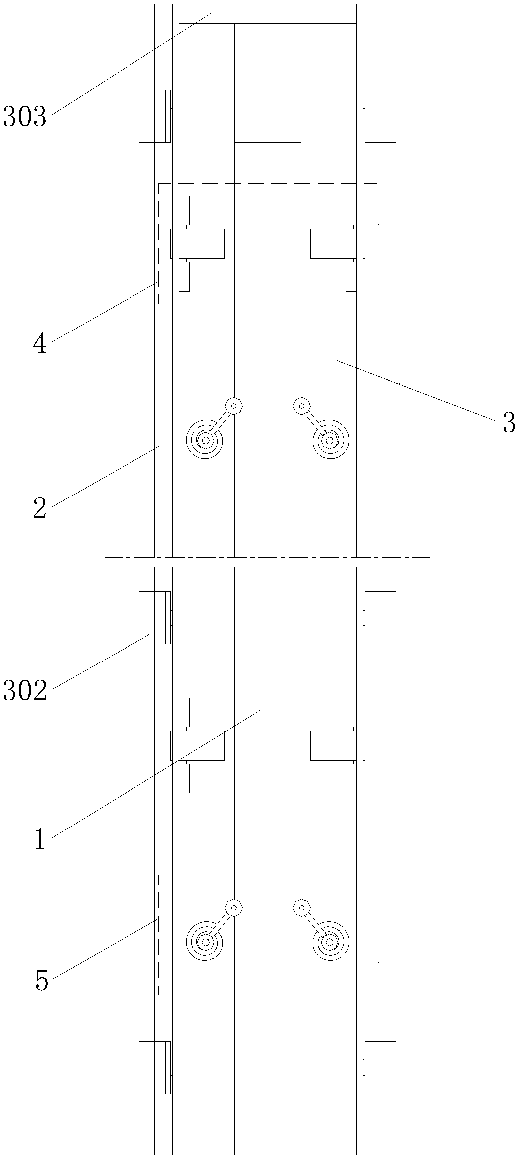
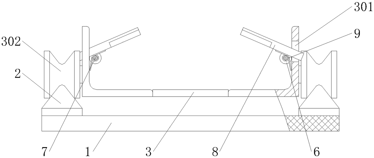
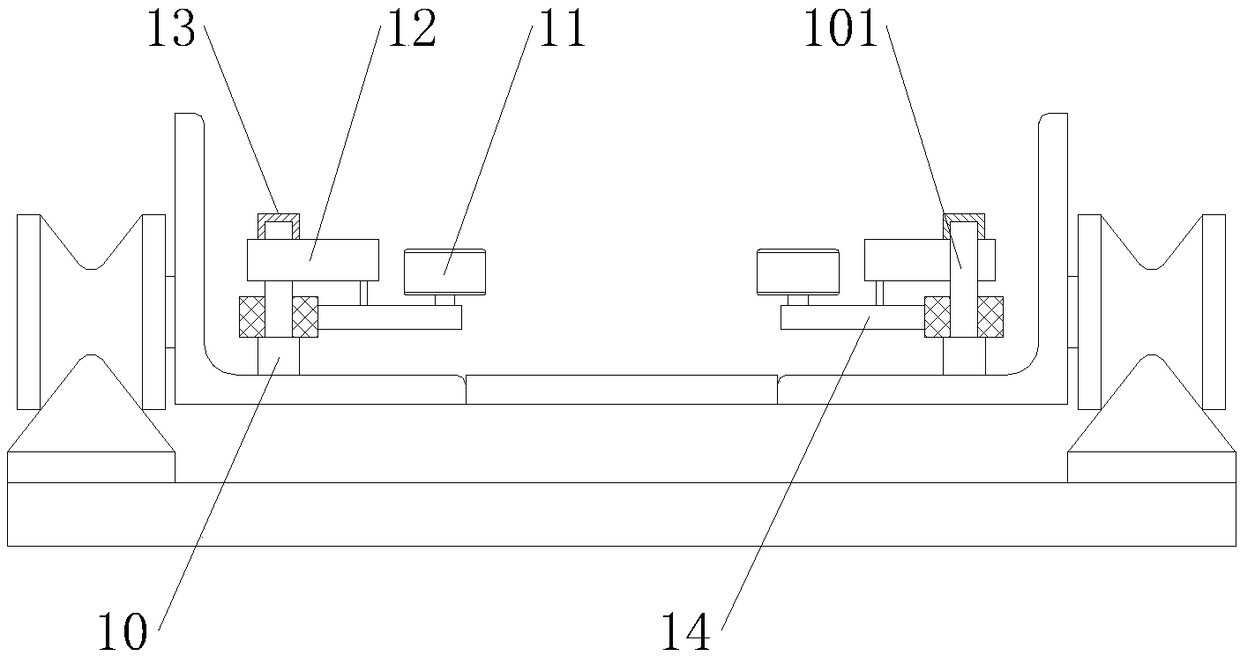
[0016] Example. A kind of bamboo sheet clamping device for drilling, constituted as figure 1 As shown, including a backing plate 1, a slidable support seat 3 is provided on the backing plate 1 via a mountain-shaped track 2, and a plurality of first clamping assemblies 4 and second clamping assemblies 5 are distributed on the support seat 3 at intervals, The first clamping assembly 4 includes a sleeve 6 fixed on both sides of the support base 3. A splint 8 is connected to the sleeve 6 through a rotating shaft 7. The middle part of the rotating shaft 7 is provided with a torsion spring 9 that cooperates with the splint 8. The outside of the splint 8 The support base 3 is provided with a limit hole 301, one end of the splint 8 extends to the outside of the support base 3 through the limit hole 301, an...


PUM


Abstract

The invention discloses a bamboo chip clamping device for drilling. The bamboo chip clamping device for drilling comprises a cushion plate; a support base capable of sliding is arranged on the cushionplate by a mountain-shaped rail; multiple first clamping modules and second clamping modules are distributed on the support base at intervals; the first clamping modules comprise sleeves fixed on thetwo sides of the support base; clamping plates are connected into the sleeves by rotating shafts; torsion springs, cooperating with the clamping plates, are arranged at the middle parts of the rotating shafts; limiting holes are formed in the support base on the outer sides of the clamping plates; one ends of the clamping plates extend to the outer side of the support base by the limiting holes,and inclined grooves are formed in the other ends of the clamping plates; the second clamping modules comprise rotating arms; the inner sides of the rotating arms are connected with the support base by stand columns; collision blocks capable of rotating are connected to the outer sides of the rotating arms; flat wire springs are arranged on the outer sides of the stand columns above the rotating arms; and the two ends of the flat wire springs are connected with the stand columns and the rotating arms. The bamboo chip clamping device for drilling has the characteristics of high positioning andmounting efficiency and high clamping stability.

Description

technical field [0001] The invention relates to a bamboo chip fixing device for a drilling machine, in particular to a bamboo chip clamping device for drilling. Background technique [0002] At present, most of the drilling methods for bamboo slices are semi-manual. When drilling each time, place the bamboo slices to be drilled on the workbench of the drilling machine, and then punch and drill the bamboo slices through the drilling machine. , and the drill bit also needs workers to manually press the bamboo slices to ensure the normal punching of the drill bit. This fixing method will not only cause a slight offset and inclination of the bamboo slices after being impacted by the drill bit, resulting in a decrease in the hole position accuracy of the bamboo slices and the hidden danger of the bamboo slices slipping away during drilling; Afterwards, the bamboo slices need to be repositioned. While reducing the drilling efficiency of the bamboo slices, the bamboo slices will c...

Claims


Application Information

Patent Timeline
IPC IPC(8): B27J1/00B27C3/00
CPCB27C3/00B27J1/00
Inventor 卢福潮王品维
Owner 安吉席丫丫竹木有限公司
Learn More