Novel automatic clamping electric carrying vehicle

An electric pallet truck and automatic clamping technology, applied in the direction of lifting devices, etc., can solve the problems of falling, valgus damage, loss of balance of goods, etc., and achieve the effect of avoiding valgus damage, high efficiency, and saving space.

Active Publication Date: 2018-09-21
河北神力索具集团有限公司
View PDF17 Cites 14 Cited by
  • Summary
  • Abstract
  • Description
  • Claims
  • Application Information

AI Technical Summary

Problems solved by technology

[0005] The purpose of the present invention is to address the deficiencies of the prior art, use the lifting work of the lifting member to drive the blocking mechanism to carry out the material blocking work on both sides of the object of the lifting member, and then cooperate with the tightening mechanism to close and clamp the object to the support frame, In this way, it solves the technical problem that the lighter goods on the fork are easy to lose balance and fall during the handling process, and then realize the effect of blocking materials on three sides, avoiding the damage of objects from turning outwards, and improving work efficiency

Method used


Image

  • Novel automatic clamping electric carrying vehicle
  • Novel automatic clamping electric carrying vehicle
  • Novel automatic clamping electric carrying vehicle

Examples


Embodiment 1

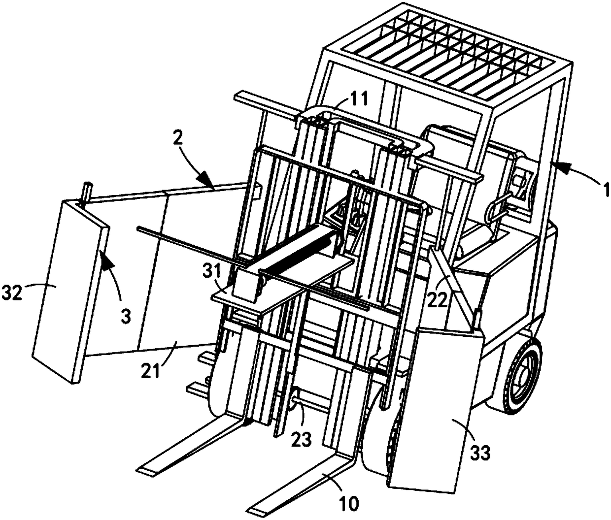
[0066] Such as figure 1 As shown, a new type of automatic clamping electric pallet truck includes a forklift 1, a support frame 11 arranged in front of the forklift 1 and a lifting member 10 arranged below the support frame 11, and also includes:

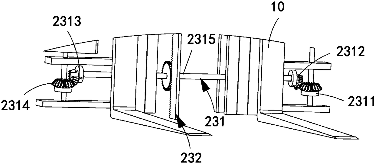
[0067] A material blocking mechanism 2, the material blocking mechanism 2 includes a side blocking assembly a21 installed on the support frame 11, a side blocking assembly b22 symmetrically arranged with the side blocking assembly a21, and a side blocking assembly b22 located between the side blocking assembly a21 and the side blocking assembly a21. The driving assembly 23 between the b22 and used to drive the side stop assembly a21 to work synchronously with the side stop assembly b22; and

[0068] The tightening mechanism 3 includes a control assembly 31 arranged on the support frame 11 and located between the side fence assembly a21 and the side fence assembly b22, a clip slidably arranged on the side fence assembly a21 The clam...

Embodiment 2

[0111] Such as Figure 10 As shown, the components that are the same as or corresponding to those in the first embodiment are marked with the corresponding reference numerals in the first embodiment. For the sake of simplicity, only the differences from the first embodiment will be described below. The difference between this embodiment two and embodiment one is:

[0112] Further, an elastic member 20 is disposed inside the material blocking plate 213 , one end of the elastic member 20 is connected to the bottom of the material blocking plate 213 and the other end is connected to the bottom of the rotating plate 321 .

[0113]In the example in this city, by setting the elastic member 20, the connection between the baffle plate 213 and the rotating plate 213 is firm, and it is not easy to slide and fall off. In addition, during the reset process, the reset feature of the elastic member 20 can be used to realize automatic reset work and improve work efficiency. efficiency.

[...


PUM


Abstract

The invention relates to a novel automatic clamping electric carrying vehicle which comprises a forklift truck, a support frame, elevating components, a blocking mechanism and a tightening mechanism.The support frame is arranged at the front of the forklift truck, the elevating components are arranged on the lower side of the support frame, the blocking mechanism comprises a side blocking assembly a, a side blocking assembly b and a driving assembly, the slide blocking assembly a is mounted on the support frame, the side blocking assembly b is symmetric with the side blocking assembly a, andthe control assembly is positioned on the side blocking assembly a and is used for driving the side blocking assembly a and the side blocking assembly b to carry out synchronous transmission; the tightening mechanism comprises a control assembly, a clamping assembly a and a clamping assembly b, the control assembly is arranged on the support frame and is positioned between the side blocking assembly a and the side blocking assembly b, the clamping assembly a is slidably arranged on the side blocking assembly a, and the clamping assembly b is slidably arranged on the side blocking assembly b. The novel automatic clamping electric carrying vehicle has the advantage that the technical problem that light goods on existing forklift trucks are easy to be out of balance and drop out in carrying procedures can be solved by the aid of the novel automatic clamping electric carrying vehicle.

Description

technical field [0001] The invention relates to the technical field of forklifts, in particular to a novel automatic clamping electric pallet truck. Background technique [0002] Forklift is an industrial handling vehicle, which refers to various wheeled handling vehicles for loading and unloading, stacking and short-distance transportation of palletized goods. It is widely used in ports, stations, airports, freight yards, factory workshops, warehouses, Distribution centers and distribution centers, etc., and can enter the cabin, carriage and container for loading and unloading and handling of palletized goods. It is an indispensable equipment for pallet transportation and container transportation. When a heavy object is used, the center of gravity of the cargo cannot be supported, resulting in the inability of the cargo to be placed on the fork stably, thus making it impossible to carry the cargo. [0003] The patent document with the patent number CN206203808U discloses a...

Claims


Application Information

Patent Timeline
Patent Type & Authority Applications(China)
IPC IPC(8): B66F9/06B66F9/18
CPCB66F9/06B66F9/18
Inventor 施华平
Owner 河北神力索具集团有限公司
Why Eureka
Try Eureka