
Longitudinal tamping device for building foundation tamping vehicle

A technology for compacting devices and foundations, which is applied in construction, electromechanical devices, and infrastructure engineering, etc., can solve the problems of limited beating and compacting and large limitations, and achieve the effects of strong practicability, strong compacting effect, and accelerated compaction efficiency

Active Publication Date: 2018-09-21
山东汶水城市建设发展有限公司
View PDF5 Cites 4 Cited by
  • Summary
  • Abstract
  • Description
  • Claims
  • Application Information

AI Technical Summary

Problems solved by technology

[0002] At present, in construction sites, before the house is built, the ground needs to be compacted. At this time, a compacting vehicle has to be used. The general compacting vehicle drives the turntable through the engine, and then drives the connected heavy block to move up. When the compacted heavy When the block moves to the highest point, the control function of the turntable on the tamping heavy block is disconnected. At this time, the tamping heavy block falls under the action of gravity, thereby performing a compacting effect on the ground. In actual work, this Relying on the single driving force of gravity, the beating and tamping of the ground is relatively limited, so it needs to work multiple times, which has great limitations

Method used


Image

  • Longitudinal tamping device for building foundation tamping vehicle
  • Longitudinal tamping device for building foundation tamping vehicle
  • Longitudinal tamping device for building foundation tamping vehicle

Examples


Embodiment Construction

[0018] The following will clearly and completely describe the technical solutions in the embodiments of the present invention with reference to the accompanying drawings in the embodiments of the present invention. Obviously, the described embodiments are only some, not all, embodiments of the present invention. Based on the embodiments of the present invention, all other embodiments obtained by persons of ordinary skill in the art without making creative efforts belong to the protection scope of the present invention.

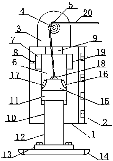
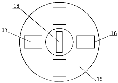
[0019] see figure 1 and figure 2 , an embodiment provided by the present invention: comprising a main hollow shell 1, one side of the main hollow shell 1 is provided with a main connecting plate 2 with an integrated structure, and the top of the main hollow shell 1 is installed with two opposite Vertical plate structure 3, two vertical plate structures 3 are installed with a rotating disk 5 through the main rotating shaft 4 inside the opposite plate body, th...


PUM


Abstract

The invention discloses a longitudinal tamping device for a building foundation tamping vehicle. The longitudinal tamping device comprises a main hollow shell. One side of the main hollow shell is provided with a main connecting plate, wherein the main hollow shell and the main connecting plate are of an integrated structure. Two opposite vertical plate structures are arranged on the top of the main hollow shell and are provided with a rotation disc in opposite plate bodies through a main rotation shaft. A movable space is arranged at the center in the main hollow shell, and the top of the main hollow shell is provided with a main through hole structure, wherein the upper portion of the main hollow shell communicates with the movable space through the main through hole structure. The magnetism generated at the bottom end of an iron core for an electromagnetic drive generation mechanism is the same as the magnetism of a permanent magnet plate on the opposite face, according to the principle that the same magnetism is in repulsion and different kinds of magnetism is in attraction, a bottom tamping plate rapidly moves downwards under the joint action of the gravity of a rectangular heavy object block and the magnetism of a permanent magnet, accordingly the tamping action is conducted on the ground, and since the drive force is generated through tamping under the joint action of the rectangular heavy object block and magnetic force, the one-time tamping effect is high, the tamping efficiency can be effectively improved, and practicability is high.

Description

technical field [0001] The invention relates to the technical field of construction equipment, in particular to a longitudinal tamping device for a building foundation tamping vehicle. Background technique [0002] At present, in construction sites, before the house is built, the ground needs to be compacted. At this time, a compacting vehicle has to be used. The general compacting vehicle drives the turntable through the engine, and then drives the connected heavy block to move up. When the compacted heavy When the block moves to the highest point, the control function of the turntable on the tamping heavy block is disconnected. At this time, the tamping heavy block falls under the action of gravity, thereby performing a compacting effect on the ground. In actual work, this Relying on the single driving force of gravity, the beating and compaction of the ground is relatively limited, so it needs to work multiple times, which has great limitations. Contents of the inventio...

Claims


Application Information

Patent Timeline
IPC IPC(8): E02D3/046H02K33/18
CPCE02D3/046E02D2200/17H01F7/0231H01F7/06
Inventor 卢洁
Owner 山东汶水城市建设发展有限公司
Learn More