Separated type tunnel arch-replacement supporting structure and construction method thereof

A support structure and separate technology, applied in the field of support structures of separate tunnels, can solve the problems of time-consuming and laborious erection of support structures, unguaranteed construction period, and incompatibility with construction requirements, etc., so as to improve construction quality and enhance The effect of strength and convenience of construction

Pending Publication Date: 2018-09-21
ANHUI HIGHWAY BRIDGE ENG CO LTD
View PDF2 Cites 6 Cited by
  • Summary
  • Abstract
  • Description
  • Claims
  • Application Information

AI Technical Summary

Problems solved by technology

[0003] The traditional arch replacement construction is generally a full hall bracket erected during the arch replacement process. This construction mode requires a lot of manpower and material resources, and is prone to accidents during the erection process, so it is no longer suitable for current construction requirements; the current mainstream The tunnel arch replacement construction adopts grouting support structure, but the layout of grouting pipes, grouting pressure, and temporary support settings will change greatly due to engineering geological conditions, tunnel forms, etc., especially the supporting structure.
For example: the arch replacement construction method mentioned in docu

Method used


Image

  • Separated type tunnel arch-replacement supporting structure and construction method thereof
  • Separated type tunnel arch-replacement supporting structure and construction method thereof
  • Separated type tunnel arch-replacement supporting structure and construction method thereof

Examples


Example Embodiment

[0031] The present invention will be further described below in conjunction with the accompanying drawings of the specification, but the protection scope of the present invention is not limited to this:

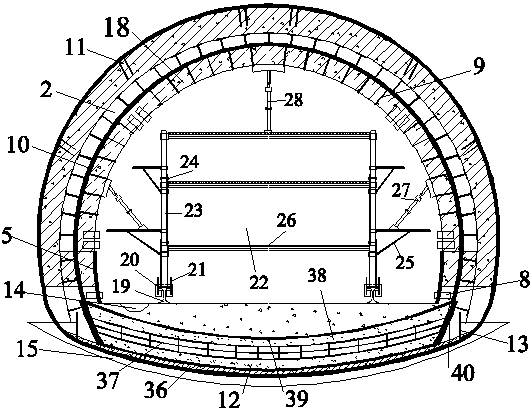
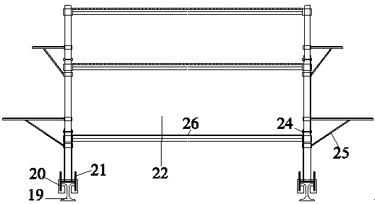
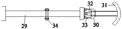
[0032] Such as Figure 1-8 As shown, the split tunnel arch-changing support structure of the present invention includes a support structure body, which is provided with a hollow grouting hole 11, an original steel frame 1, a new steel frame 2, and a small grouting hole. Conduit 4, low side wall 5, temporary invert structure, steel mesh 10, hollow grouting hole 11, invert 12 and secondary lining structure 18. The temporary invert structure is composed of I-shaped steel frame 6 and lock-foot steel pipe 7. It is erected at the middle height of the tunnel and reinforced by wooden wedges; the hollow grouting hole 11 is reserved behind the initial support structure, and the small grouting pipe 4 is arranged at the circumferential position of the tunnel. After replacing the new steel f...


PUM


Abstract

The invention relates to a separated type tunnel arch-replacement supporting structure and a construction method thereof. The supporting structure comprises a supporting structure body. A cavity grouting hole, an original steel frame, a new steel frame, a grouting small guide pipe, dwarf side walls, a temporary inverted arch structure, a reinforcing steel bar net, an inverted arch and a secondarylining structure are arranged on the supporting structure body. The temporary inverted arch structure is composed of an I-type steel frame and lock pin steel pipes and is erected in the middle heightposition of a tunnel and reinforced through a wood wedge. The inverted arch is located on the lower side of the bottom face of the tunnel. The original steel frame and the new steel frame are erectedin the tunnel. The grouting small guide pipe is arranged in the cross section of the original steel frame. The dwarf side walls are located on the two sides in the tunnel. The grouting steel floral pipes are arranged the arch legs and arc waist of the tunnel and the corners of the dwarf walls. The reinforcing steel bar net is arranged between the steel frames. The secondary lining structure is located on the inner side of the reinforcing steel bar net. Compared with existing arch-replacement construction, the problems of time and labor waste, safety and quality are solved, and the remarkable economic benefits are obtained.

Description

technical field [0001] The invention relates to a supporting structure of a split tunnel, in particular to a split tunnel arch changing supporting structure and a construction method thereof. Background technique [0002] The center of the national development strategy is shifting from the eastern coastal areas to the central and western inland areas, which requires vigorous development of transportation. However, the central and western parts of my country are mountainous, and tunnels need to be built to cross the mountainous areas in the process of building roads or railways. The safety problems of the tunnel mainly include cracks and deformations during the construction period. If they are not controlled and repaired, it will have a major impact on the safety of the entire structure of the tunnel. Therefore, it is necessary to replace the arch at the deformation of the initial support structure of the tunnel. [0003] The traditional arch replacement construction is gener...

Claims


Application Information

Patent Timeline
IPC IPC(8): E21D11/10E21D20/02E21D11/38E21D9/12E21F17/18
CPCE21D9/122E21D11/10E21D11/38E21D20/02E21F17/18
Inventor 杜海峰孙学军彭申凯任杰刘要武杨文柱崔健
Owner ANHUI HIGHWAY BRIDGE ENG CO LTD
Why Eureka
Try Eureka