A sound source localization calibration method
A calibration method and a technology for sound source localization, which can be applied in positioning, instruments, measuring devices, etc., can solve the problems of small calculation amount and inability to monitor thunderstorm clouds, etc., and achieve the effect of low calculation amount, high positioning accuracy and small error.
- Summary
- Abstract
- Description
- Claims
- Application Information
AI Technical Summary
Problems solved by technology
Method used
Image

Examples
Embodiment 1
[0023] Embodiment 1 (thunder sound source localization)
[0024] A kind of sound source localization calibration method based on microphone observation angle of view of the present invention, specifically comprises following process:
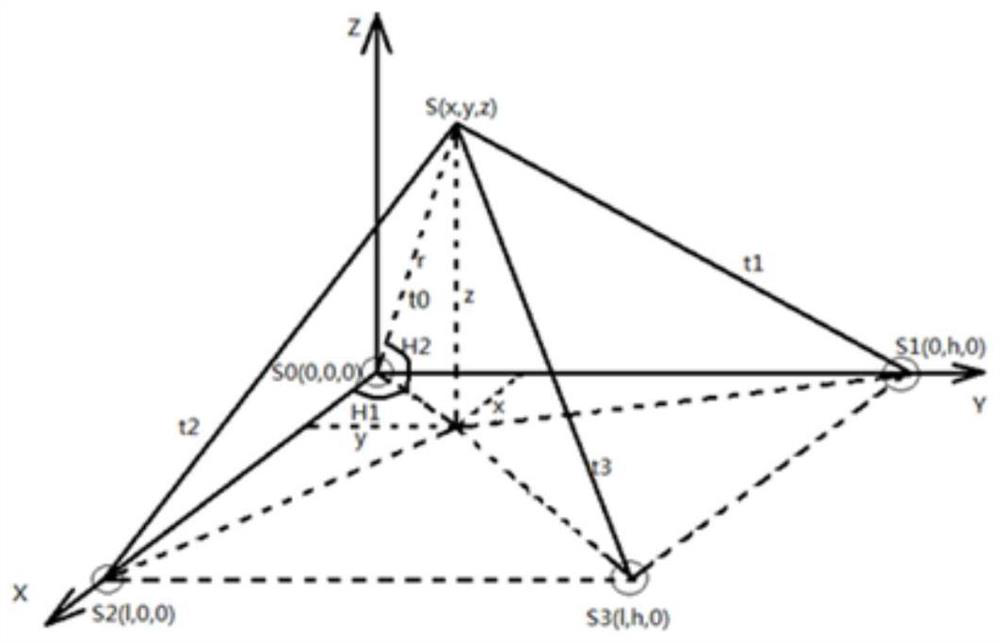
[0025] Step 1, give the first thunder sound source localization inversion algorithm (such as figure 1 ), which is based on the four-element microphone array model, the propagation velocity of the thunder sound source is c, assuming that the spatial position of the sound source S is (x, y, z), r is the distance from the sound source to the coordinate origin, and z should be greater than zero. The time for S to propagate to S0(0,0,0), S1(0,h,0), S2(l,0,0), S3(l,h,0) is t respectively 0 , t 1 , t 2 , t 3 Combined with the spatial positions of the four microphones set in the model, three relative delay values are obtained: Δt 1 = t 1 -t 0 , Δt 2 = t 2 -t 0 , Δt 3 = t 3 -t 0 .
[0026] Step 2, from figure 1 The distances from S to S...
Embodiment 2
[0062] Embodiment 2 (spatial sound source localization)
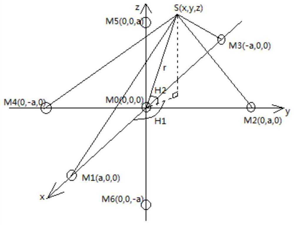
[0063] Step 11, give the second sound source localization inversion algorithm (such as figure 2 shown), which is based on the seven-element cross matrix model, refer to figure 2 , let the sound propagation speed be c, the spatial position of the sound source S be (x, y, z), and r be the sound source to the coordinate origin M 0 the distance. S propagates to microphone M 0 (0,0,0), M 1 (a,0,0), M 2 (0,a,0), M 3 (-a,0,0), M 4 (0,-a,0), M 5 (0,0,a), M 6 The time of (0,0,-a) is t respectively 0 , t 1 , t 2 , t 3 , t 4 , t 5 , t 6 , and set 5 sets of relative delay values according to the model: T 1 = t 1 -t 0 ,T 2 = t 2 -t 0 , T 3 = t 3 -t 0 ,T 4 = t 4 -t 0 ,T 5 = t 6 -t 5 . h 1 The angle between S and the positive semi-axis of x is called the horizontal declination, and the range is between [0,360°]; H 2 is the elevation angle formed by S and the x-y-0 plane, the range is between [-90°,...
Embodiment 3
[0107] Embodiment 3 (sound source localization calibration)
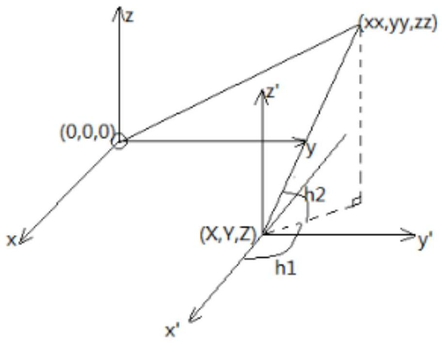
[0108] Step 25, the focus of the steps in the above two embodiments is to obtain the inverted sound source coordinates, so as to perform subsequent calibration. Assume that the observation angle N is located in the coordinate system of the original microphone array, denoted as (X, Y, Z). refer to image 3 , convert (X, Y, Z) to (0,0,0) and establish a new coordinate system, then (xx, yy, zz) is converted to (xx-X, yy-Y, zz-Z), will (xx-X,yy-Y,zz-Z) is equivalent to (XX,YY,ZZ). Let the horizontal declination (the angle with the positive semi-axis of the new coordinate system x') be h 1 , the range is between [0,360°]; the elevation angle (the angle with the new coordinate system x'-y'-0 plane) is h 2 , the range is between [-90°,90°]. h 2 If the value of is positive, it means that the sound source is above the plane where the viewing angle N is located, and if it is negative, it means that it is below the plane...
PUM
 Abstract
Description
Claims
Application Information
 - R&D
- Intellectual Property
- Life Sciences
- Materials
- Tech Scout
- Unparalleled Data Quality
- Higher Quality Content
- 60% Fewer Hallucinations
Browse by: Latest US Patents, China's latest patents, Technical Efficacy Thesaurus, Application Domain, Technology Topic, Popular Technical Reports.
© 2025 PatSnap. All rights reserved.Legal|Privacy policy|Modern Slavery Act Transparency Statement|Sitemap|About US| Contact US: help@patsnap.com