Shifting register, driving method thereof, Gate On Array and display device

A shift register, sub-circuit technology, applied in static memory, digital memory information, instruments, etc., can solve problems such as drift, and achieve the effect of reducing noise

Active Publication Date: 2018-09-21
BOE TECH GRP CO LTD +1
View PDF4 Cites 15 Cited by
  • Summary
  • Abstract
  • Description
  • Claims
  • Application Information

AI Technical Summary

Problems solved by technology

However, under the influence of long-term pulses on the gate of the Thin Film Trans...

Method used


Image

  • Shifting register, driving method thereof, Gate On Array and display device
  • Shifting register, driving method thereof, Gate On Array and display device
  • Shifting register, driving method thereof, Gate On Array and display device

Examples


Embodiment 1

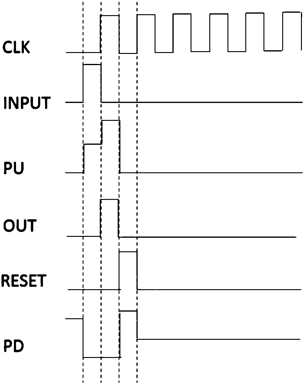
[0068] The present embodiment provides a shift register and a corresponding driving method thereof, which can effectively avoid threshold drift of thin film transistors in the shift register and provide better noise reduction effects.

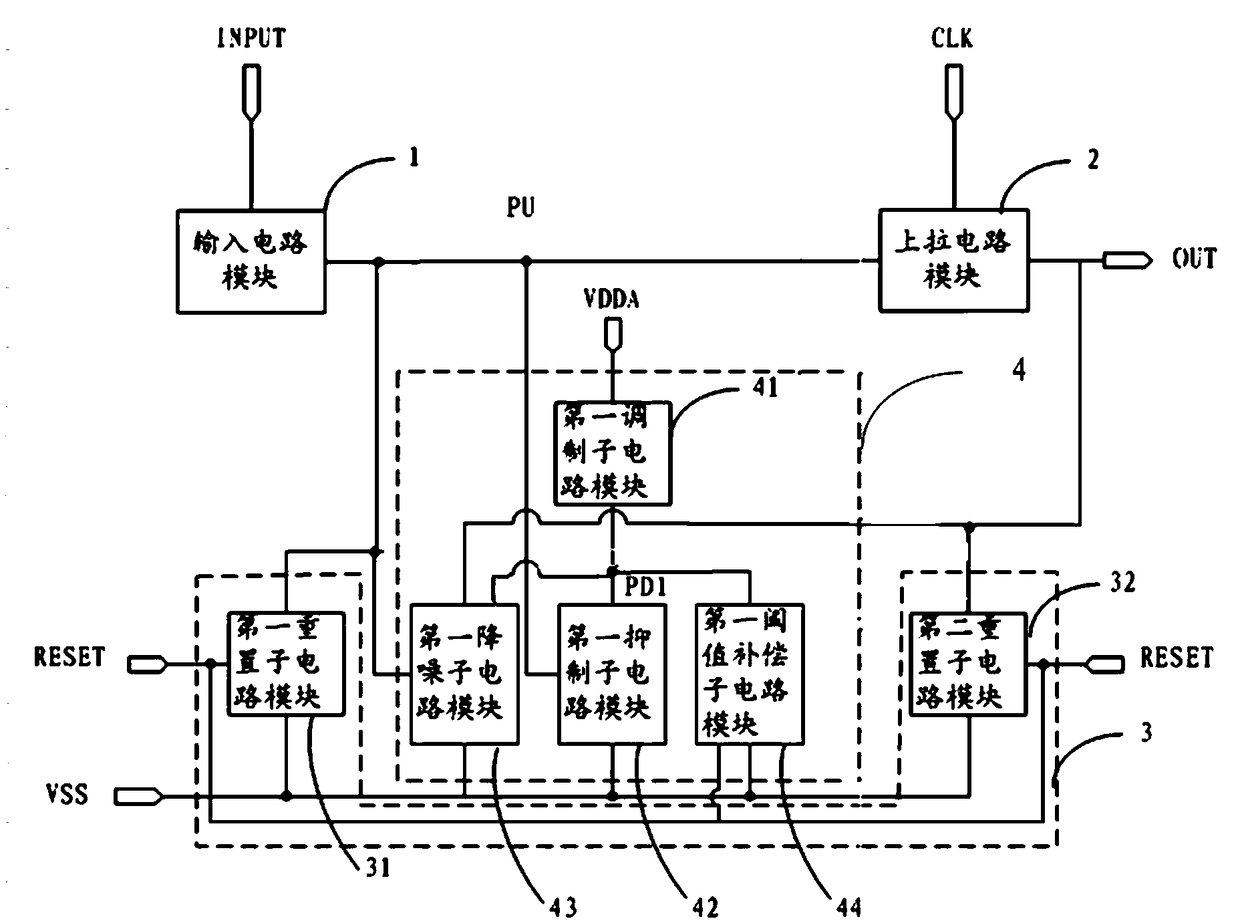
[0069] like figure 1 As shown, the shift register includes an input circuit module 1, a pull-up circuit module 2, a reset circuit module 3 and a noise reduction circuit module 4, wherein:

[0070] The input circuit module 1 is connected to the input signal terminal and the pull-up node, and is used to pull the pull-up node signal high under the control of the input signal, that is, to charge the pull-up node;

[0071] The pull-up circuit module 2 is connected with the clock signal terminal, the output signal terminal and the pull-up node, and is used to output the shift signal and pull the pull-up node signal high again, that is, pull the pull-up node high again, and complete the shifting at the same time. The output process of the bit registe...

Embodiment 2

[0091] The present embodiment provides a shift register and a corresponding driving method thereof, which can effectively avoid threshold drift of thin film transistors in the shift register and provide better noise reduction effects.

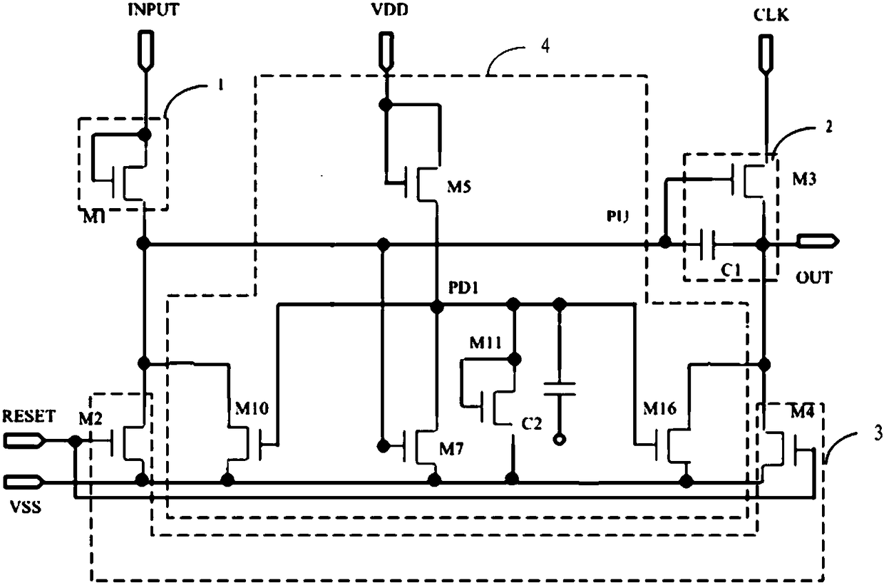
[0092] The difference between the shift register of this embodiment and Embodiment 1 is that the noise reduction circuit module in the shift register of this embodiment includes a first noise reduction circuit module and a second noise reduction circuit module with the same structure, two groups of noise reduction circuit modules The functions of the circuit modules are the same, and the two groups of noise reduction circuit modules work alternately, so that the high level time of the transistor (M9 / M17 or M16 / M10) in the noise reduction circuit module can be reduced to half of the original, avoiding the long-term Serious drift caused by high-level signals.

[0093] like Figure 4 As shown, the shift register includes an input circuit modu...

Embodiment 3

[0127] This embodiment provides a gate driving circuit, including the shift register in Embodiment 1 or Embodiment 2.

[0128] In this gate drive circuit, multiple shift registers are connected in cascade, such as Figure 7 As shown, the output signal terminal of the upper-stage shift register is connected to the input circuit module of the shift register, and the output signal of the output signal terminal of the next-stage shift register is connected to the reset circuit module and the noise reduction circuit module of the shift register .

[0129] That is to say, for the shift register in the gate driving circuit, the input signal INPUT of a certain stage is the output signal OUT of the previous stage, and the reset signal RESET is the output signal OUT of the next stage.


PUM


Abstract

The invention belongs to the technical field of display, and relates to a shifting register, a driving method thereof, a gate on array and a display device. The shifting register comprises an input circuit module, a pull-up circuit module, a reset circuit module and a noise reduction circuit module, wherein the input circuit module is connected with an input signal end and a pull-up node, and is used for pulling up a pull-up node signal under the control of an input signal; the pull-up circuit module is connected with a clock signal end, an output signal end and the pull-up node, and is used for outputting a shifting signal and pulling up the pull-up node signal for the second time; the reset circuit module is connected with a reset signal end, the pull-up node, the output signal end and alow-voltage signal end, and is used for lowering the output signal end and the pull-up node; the noise reduction circuit module is connected with a modulating voltage signal end, the low-voltage signal end, the output signal end and the pull-up node, and is used for continuously lowering the output signal end and the pull-up node. Through the adoption of the shifting register disclosed by the invention, threshold shift of a thin-film transistor can be effectively avoided, and a noise reduction effect is better.

Description

technical field [0001] The invention belongs to the field of display technology, and in particular relates to a shift register, a driving method thereof, a gate driving circuit and a display device. Background technique [0002] In the field of liquid crystal displays, the circuit that integrates the gate drive circuit into the liquid crystal panel (Gate On Array, referred to as GOA) has been widely used. The GOA circuit inherits the gate drive circuit on the array substrate to replace the traditional Gate IC. It has the advantages of reducing production costs, reducing production procedures and the like. [0003] Usually, the GOA circuit is a progressive scanning circuit, and the signal needs to be reset after the output of a certain row is completed. After the reset is completed, in order to avoid noise output, noise reduction is also required. However, under the influence of long-term pulses, the threshold voltage Vth of the gate of the thin film transistor (Thin Film T...

Claims


Application Information

Patent Timeline
IPC IPC(8): G09G3/36G11C19/28
CPCG09G3/3677G11C19/28G09G2310/0286G09G3/3674G09G3/3696G09G2300/0426G09G2310/08G09G2320/045
Inventor 刘金良张淼傅武霞
Owner BOE TECH GRP CO LTD
Why Eureka
Try Eureka