An infrared controllable automatic plug device

An infrared, automatic technology, applied in the direction of coupling devices, parts of connecting devices, devices for connecting/disconnecting connecting parts, etc., can solve the problems of low degree of automation, low degree of automation, troublesome use, etc., and achieve high degree of automation , reliable performance

Inactive Publication Date: 2019-11-01
CHINA UNIV OF GEOSCIENCES (WUHAN) +1
View PDF6 Cites 0 Cited by
  • Summary
  • Abstract
  • Description
  • Claims
  • Application Information

AI Technical Summary

Problems solved by technology

[0002] Most of the traditional latches are manual latches, which are cumbersome to use. Although there are some electric latches, their structure is relatively complicated, the degree of automation is not high, and the production cost is expensive. The latches are generally divided into two parts, one with a movable rod, and the other One part is a bolt hole. The bolt plays an irreplaceable role in many workplaces, especially the automatic bolt. Most of the existing automatic bolts are used on doors and windows. Strictly speaking, they only have the function of relative movement. After the installation is stable, If the pin needs to be removed again, it needs to be disassembled manually, and when it is used again, it also needs to be installed manually. However, the pin is also required when manual operation is impossible or inconvenient in the case of automatic positioning of the hole shaft in the box sealing member or high place. , the existing automatic plug products have a low degree of automation and do not have remote control functions, so they cannot meet the needs of this situation

Method used


Image

  • An infrared controllable automatic plug device
  • An infrared controllable automatic plug device
  • An infrared controllable automatic plug device

Examples


Embodiment Construction

[0025] In order to make the purpose, technical solution and advantages of the present invention clearer, the embodiments of the present invention will be further described below in conjunction with the accompanying drawings.

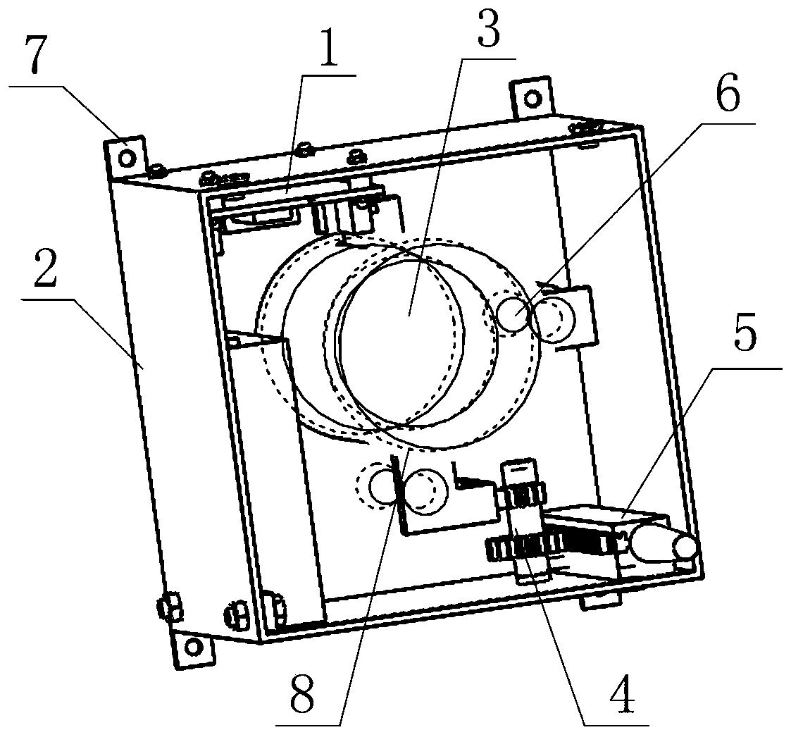
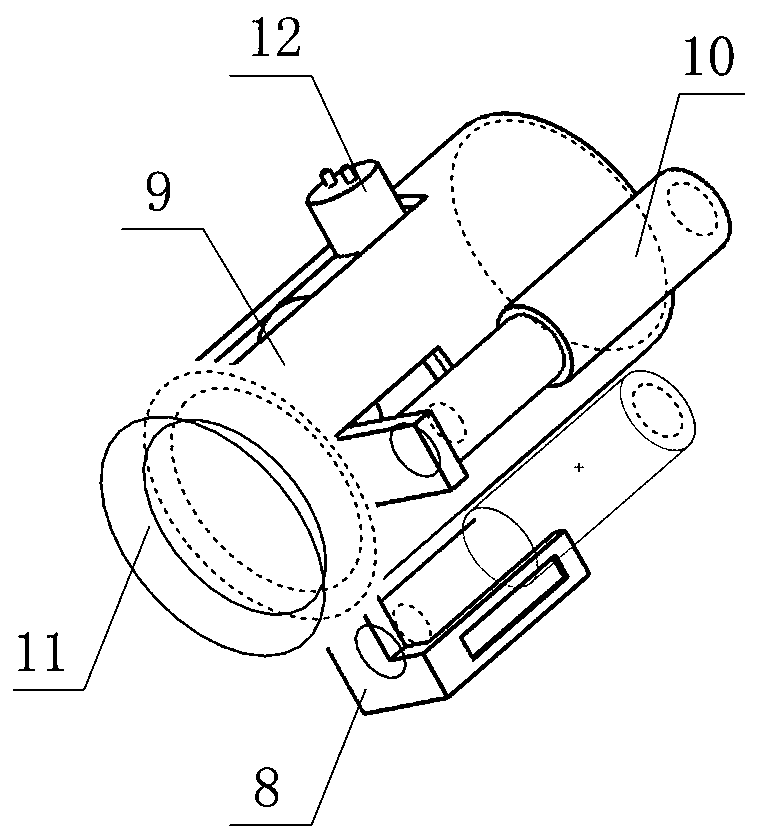
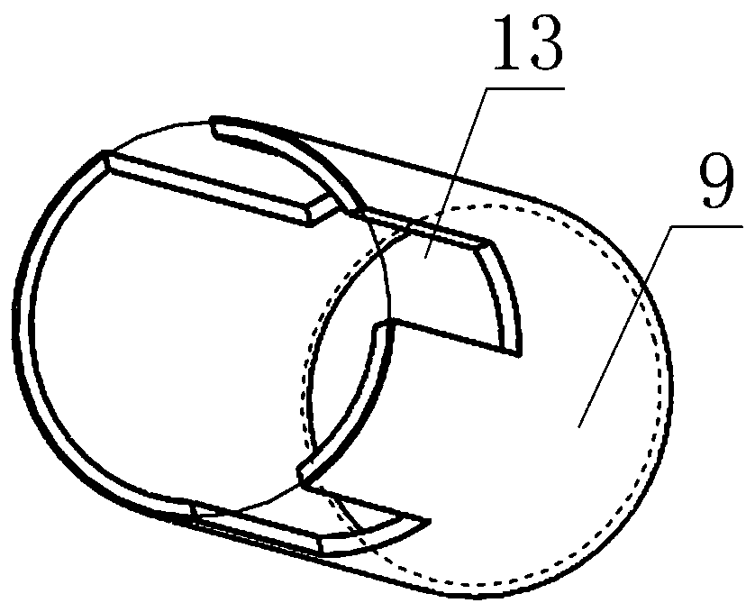
[0026] Please refer to Figure 1 to Figure 6 , the embodiment of the present invention provides an infrared controllable automatic plug device, including a plug body and an infrared drive circuit 1 , the plug body includes a housing 2 , an electromagnetic repulsion mechanism 3 , a multiplier mechanism 4 and a plug assembly 5 .

[0027] The housing 2 includes a cuboid cavity and an end cover, the upper port edge of the cavity is provided with a slot, and the end cover is provided with a through hole, and the end cover is snapped into the slot to seal the cavity , the four top corners of the bottom surface of the cavity are provided with positioning feet 7, which is convenient for positioning and installation of the device during use;

[0028] The electro...


PUM


Abstract

The invention provides an infrared controllable automatic plugging pin device. The device comprises a plugging pin body and an infrared driving circuit; the plugging pin body comprises a shell, an electromagnetic attraction and repulsion mechanism, a stroke doubling mechanism and a plugging pin assembly; the electromagnetic attraction and repulsion mechanism comprises a permanent magnet connectionring, a guide cylinder and spring tubes; the magnet connection ring is accommodated in the guide cylinder and moves axially along the guide cylinder; two ends of each spring tube are respectively connected with the magnet connection ring and the bottom of the shell; a coil is fixed in the guide cylinder; a permanent magnet is fixed to the bottom of the permanent magnet connection ring; the permanent magnet is opposite to the coil; the stroke doubling mechanism is connected with the magnet connection ring and the plugging pin assembly and performs transmission; the plugging pin assembly is fixed to the side wall of the shell; the plugging pin assembly comprises a bolt pin; and the infrared driving circuit is connected with the coil, receives external infrared signals and controls the coilto be energized or de-energized, thereby controlling the bolt pin to extend or retract. With the infrared controllable automatic plugging pin device of the invention adopted, the remote control of theplugging pin is realized. The performance of the device is reliable; the device is suitable for situations where manual operation is inconvenient or impossible; and the degree of automation of the device is high.

Description

technical field [0001] The invention relates to a plug, in particular to an infrared controllable automatic plug device. Background technique [0002] Most of the traditional latches are manual latches, which are cumbersome to use. Although there are some electric latches, their structure is relatively complicated, the degree of automation is not high, and the production cost is expensive. The latches are generally divided into two parts, one with a movable rod, and the other One part is a bolt hole. The bolt plays an irreplaceable role in many workplaces, especially the automatic bolt. Most of the existing automatic bolts are used on doors and windows. Strictly speaking, they only have the function of relative movement. After the installation is stable, If the pin needs to be removed again, it needs to be disassembled manually, and when it is used again, it also needs to be installed manually. However, the pin is also required when manual operation is impossible or inconven...

Claims


Application Information

Patent Timeline
Patent Type & Authority Patents(China)
IPC IPC(8): H01R13/62H01R13/66
CPCH01R13/6205H01R13/665H01R13/6683
Inventor 卢春华左国勇孙云志肖冬顺马明曾立新
Owner CHINA UNIV OF GEOSCIENCES (WUHAN)
Why Eureka
Try Eureka