
Cleaning device for control cabinet

A cleaning device and control cabinet technology, applied in the field of electrical cabinets, can solve the problems of untimely and effective treatment of snow accumulation, easy access of snow water personnel, damage of electrical components, etc., and achieve easy replacement and maintenance, convenient cleaning and safe use Effect

Pending Publication Date: 2018-09-21
GUIZHOU UNIV
View PDF12 Cites 2 Cited by
  • Summary
  • Abstract
  • Description
  • Claims
  • Application Information

AI Technical Summary

Problems solved by technology

The existing electrical control cabinet does not have the function of snow plowing, and the accumulated snow on the electrical control cabinet cannot be dealt with in a timely and effective manner. As a result, when the snow melts, people with snow water can easily enter the electrical control cabinet, causing damage to the electrical control cabinet. Damage to internal electrical components

Method used


Image

  • Cleaning device for control cabinet
  • Cleaning device for control cabinet
  • Cleaning device for control cabinet

Examples


Embodiment 1

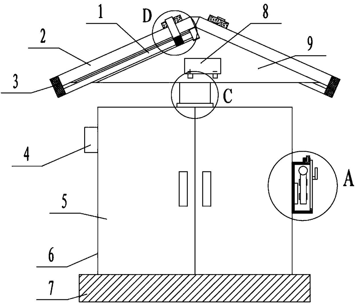
[0025] Embodiment 1: as Figure 1-9 As shown, a cleaning device for a control cabinet includes a cleaning head 10, a connecting rod 11, a slider 12 and a drive motor 13. Both ends of the cleaning head 10 are connected to the front and rear sides of the top cover 9 through linear bearings 30, and the outer side of one end is connected to the front and rear sides of the top cover 9 through a connecting rod 11. Fixedly connected to the slider 12, the slider 12 is equipped with a lead screw nut pair to drive it to move, the screw nut pair is connected with a drive motor 13, and the drive motor 13 is fixedly connected to the side of the top cover 9, the screw nut pair The pair includes a lead screw 1 and a screw nut 31. Both ends of the lead screw 1 are connected to the bearing seat 3, and one end extends out of the bearing seat and is connected to the drive motor 13 through a coupling. The bearing seat 3 is fixedly connected to the top cover 9, and the straight line The two ends o...

Embodiment 2

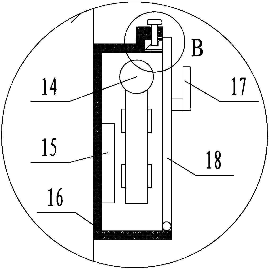
[0030] Embodiment 2: as Figure 1-9 As shown, a control cabinet includes a cabinet body 6, the cabinet body 6 is fixedly connected to the base 7, two movable doors 5 are arranged on the front side of the cabinet body 6, LED lights 4 are arranged on the left side, and the side of the cabinet body 6 An alarm box 16 is provided, and the outer end of the alarm box 16 is provided with a sealed door 18, and a microphone 14 is installed inside, and the microphone 14 is electrically connected to the input end of the controller 15, and the communication end of the controller 15 is connected to a 4G module, and the 4G module is connected to the mobile The terminal is connected, and the outer surface of the cabinet 6 is evenly sprayed with waterproof paint, and the controller adopts AT89C52.

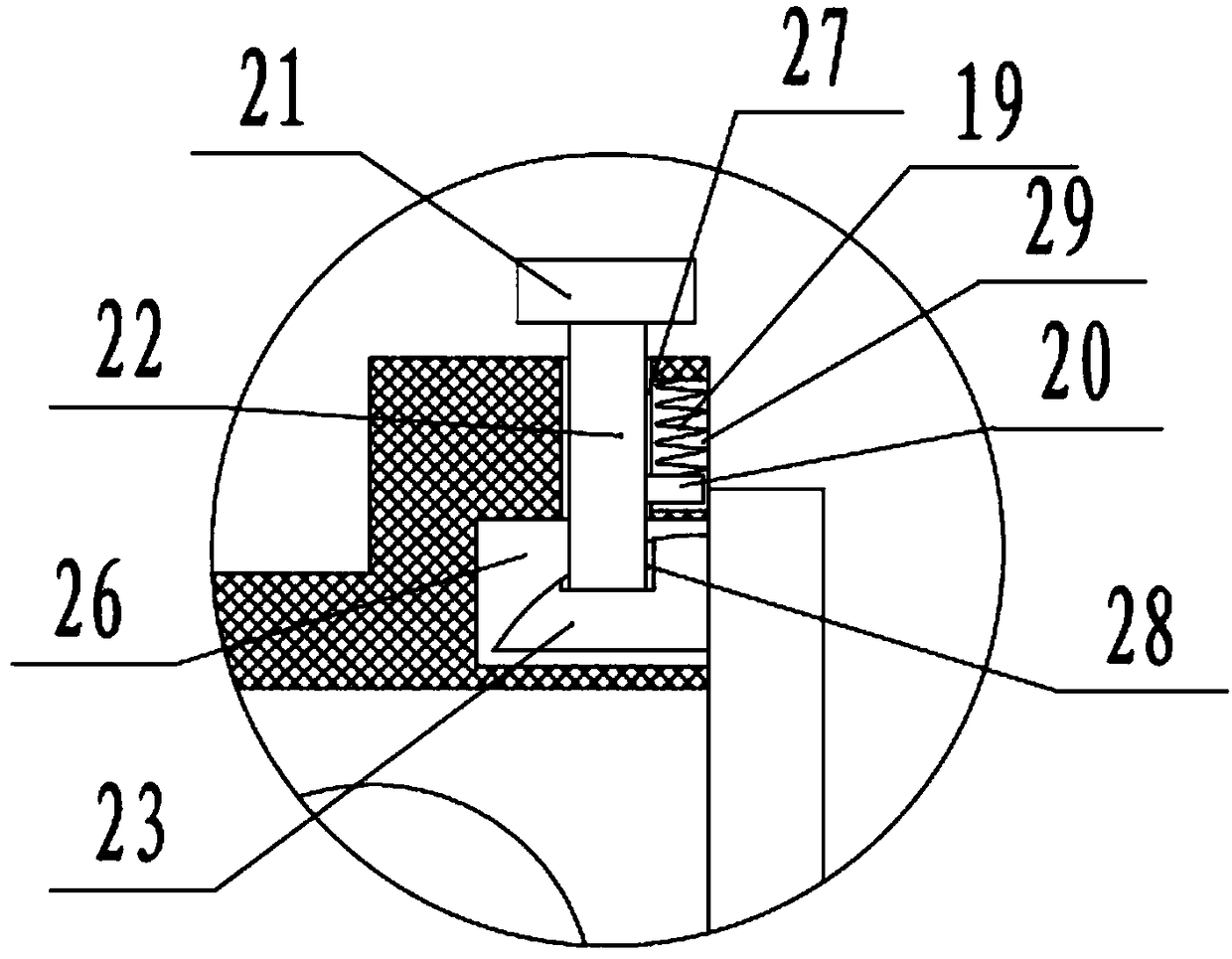
[0031] Preferably, the lower end of the airtight door 18 is hinged on the end edge of the alarm box 16, and the upper end is connected to the alarm box 16 through a clamping device.

[0032] Prefe...


PUM


Abstract

The invention discloses a cleaning device for a control cabinet, comprising a cleaning head, a connecting rod, a sliding block and a driving motor, wherein two ends of the cleaning head are connectedto the front and rear sides of a top cover by a linear bearing, the outer side of one end is fixedly connected to the sliding block by the connecting rod, a screw rod and screw nut pair for driving the sliding block to move is arranged on the sliding block, the screw rod and screw nut pair is connected with a driving motor, and the driving motor is fixedly connected to the side face of the top cover. According to the invention, the cleaning device formed by the cleaning head, the connecting rod, the sliding block and the driving motor is adopted, and is electrically driven, thus saving time and labor, being sanitary and convenient to clean, avoiding damage of electrical apparatus elements in an electric control cabinet caused by inflow of snow water into the electrical apparatus elements,and being safer to use.

Description

technical field [0001] The invention relates to a cleaning device for a control cabinet, which belongs to the technical field of electrical cabinets. Background technique [0002] The control cabinet is to assemble the switchgear, measuring instrument, protective device and auxiliary equipment in the closed or semiclosed metal cabinet or on the screen width according to the requirements of electrical wiring. and the safety of surrounding equipment. During normal operation, the circuit can be connected or disconnected by means of a manual or automatic switch. Cut off the circuit or alarm with the help of protective electrical appliances in case of failure or abnormal operation. Various parameters in operation can be displayed by means of measuring instruments, and some electrical parameters can also be adjusted to prompt or send out signals for deviations from normal working conditions. The existing electrical control cabinet does not have the function of snow plowing, and...

Claims


Application Information

Patent Timeline
IPC IPC(8): H02B1/28H02B1/30
CPCH02B1/28H02B1/306
Inventor 魏文兵韩松刘芸
Owner GUIZHOU UNIV
Learn More