Tubeless liquid cooling heat dissipating system
A technology of liquid cooling and heat dissipation device, applied in cooling/ventilation/heating transformation, tubular elements, indirect heat exchangers, etc., can solve the problems of inconvenient installation and operation, poor installation flexibility, single design form, etc., to save space. Space, installation and use are flexible and convenient
- Summary
- Abstract
- Description
- Claims
- Application Information
AI Technical Summary
Problems solved by technology
Method used
Image

Examples
Embodiment Construction
[0046] In order to make the purpose, technical solutions and advantages of the present invention clearer, the various embodiments to be described below will refer to the corresponding drawings, and these drawings constitute a part of the embodiments, which describe various possible implementations of the present invention. kind of embodiment. It is to be understood that other embodiments may be utilized or structural and functional modifications may be made to the embodiments set forth herein without departing from the scope and spirit of the present invention.
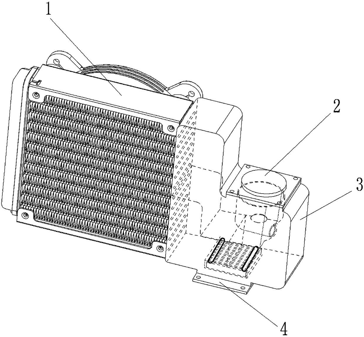
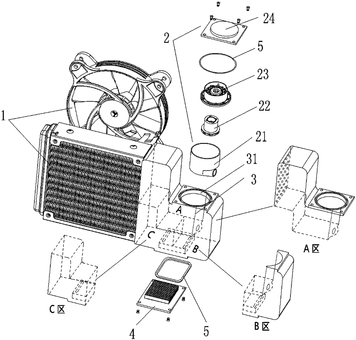
[0047] refer to Figure 1 to Figure 3As shown, a tubeless liquid-cooled heat dissipation system of the present invention includes a heat dissipation device 1, a pumping device 2, a water tank 3, and a heat absorbing device 4. The pumping device 2, the heat absorbing device 4, the heat sink 1 and the water tank 3. It is integrated and connected in a pipeless manner, that is, the connecting pipes between the parts are ...
PUM
 Abstract
Description
Claims
Application Information
PatSnap Eureka turns technology decisions into work you can execute. Powered by our Innovation Knowledge Graph, it runs expert workflows across engineering, life sciences, materials and intellectual property. Get your review-ready output in minutes.


