Tilling cutter of mini-tiller

A technology of micro tillage machine and tiller knife, which is applied in the fields of tillage machines, agricultural machinery and implements, etc. It can solve the problems of micro tillage machine power reduction, weed entanglement, etc., and achieve the effect of reducing power consumption and increasing the degree of fertility

Pending Publication Date: 2018-09-25
CHONGQING ZHUOGE HAOSI MACHINERY
View PDF1 Cites 0 Cited by
  • Summary
  • Abstract
  • Description
  • Claims
  • Application Information

AI Technical Summary

Problems solved by technology

[0005] The invention discloses a tiller blade for a tiller, which aims to solve the problem that the power of

Method used


Image

  • Tilling cutter of mini-tiller
  • Tilling cutter of mini-tiller

Examples


Embodiment Construction

[0025] The following is further described in detail by specific embodiments:

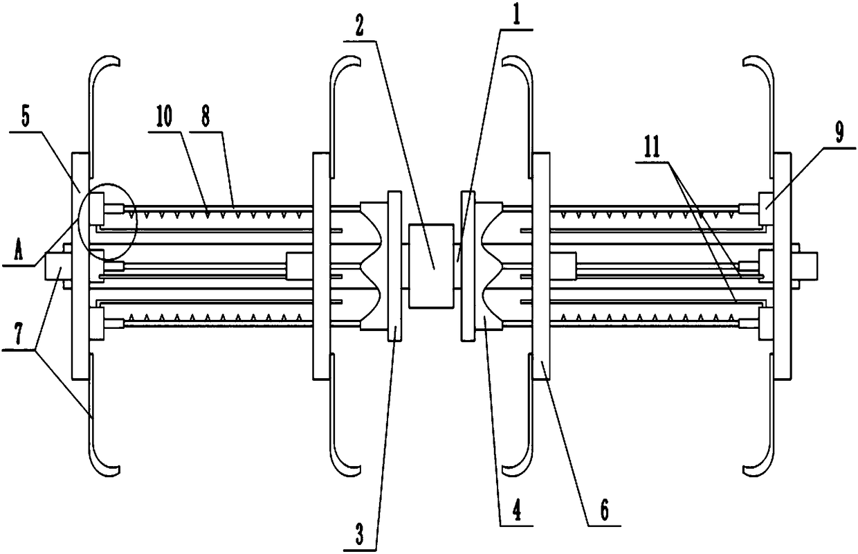
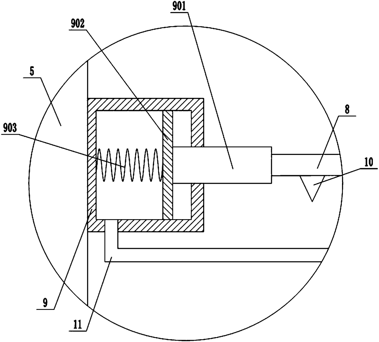
[0026] The reference signs in the drawings of the description include: output shaft 1, tooth portion 2, idler gear 3, cylindrical cam 4, first cutter head 5, second cutter head 6, blade 7, anti-winding rod 8, cylinder 9, Cutter 10, pipeline 11, piston rod 901, piston plate 902, return spring 903.

[0027] The example is basically as attached figure 1 and figure 2 Shown: a tiller blade for a micro tillage machine, including an output shaft 1, the middle part of the output shaft 1 is provided with a tooth part 2 connected with a gear of the micro tillage machine power device.

[0028] On the output shaft 1, there are two cutterhead groups facing the tooth part 2, and an idle gear 3 is set between the cutter head group and the tooth part 2. The idle gear 3 has a threaded hole. The provided threaded hole is used to fix the idler gear 3 on the tiller with screws; the hollow cylindrical cam 4 is welde...


PUM


Abstract

The invention belongs to the technical field of agricultural machinery, and particularly discloses a tilling cutter of a mini-tiller. According to the tilling cutter, a tooth part is arranged in the middle of an output shaft; two cutter head sets are arranged on the output shaft; an idler gear with a cylindrical cam is arranged between each cutter head set and the tooth part; each cutter head setcomprises a first cutter head, a second cutter head and a plurality of anti-winding rods; a plurality of air cylinders are arranged on the surface, close to the tooth part, of each first cutter head;a plurality of through holes are formed in each second cutter head; a plurality of blades are fixed on the first cutter heads and the second cutter heads; one ends of the anti-winding rods are fixed to piston rods of the corresponding air cylinders; the other ends of the anti-winding rods penetrate through the corresponding through holes to abut against the cylindrical cams; a plurality of cuttingknives are fixed to the anti-winding rods; reset springs are fixed between piston plates of the air cylinders and the cavity walls of rodless cavities of the air cylinders; pipelines are communicatedwith the rodless cavities of the air cylinders and are fixed to the second cutter heads; and pipe orifices of the pipelines face the tooth part. The tilling cutter aims to solve the problems that when in the tilling process of a mini-tiller, the power of the mini-tiller is reduced due to the fact that weeds are wound around an output shaft of the tilling cutter.

Description

technical field [0001] The invention belongs to the technical field of agricultural machinery, and specifically discloses a tiller blade for a tiller. Background technique [0002] The traditional three-piece anti-winding cultivating knife device includes the main cutter shaft, on which three cutter heads are coaxially installed, two of which are located at both ends of the main cutter shaft, and the third cutter head is set in the middle of the main cutter shaft . Simultaneously, a secondary shaft can also be connected to one end of the main cutter shaft, and a cutter head is set on the auxiliary shaft, and three plow knives are installed on each of the cutter heads, and the handle of the plow knife is fixed on the cutter head. The cutter body of the tiller is suspended in the air, and there is a cutting edge on one side of the cutter body; the type of the tiller can be a dry land knife or a wet land knife. In order to prevent the straw from being entangled on the main cu...

Claims


Application Information

Patent Timeline
IPC IPC(8): A01B33/16A01B33/10A01B33/12
CPCA01B33/16A01B33/103A01B33/12
Inventor 刘国印
Owner CHONGQING ZHUOGE HAOSI MACHINERY
Why Eureka
Try Eureka