Multifunctional electric rotary mop

An electric rotating, multi-functional technology, applied in the field of cleaning tools, can solve the problems of reducing the number of replacement cleaning heads, poor cleaning effect on stubborn stains, and increasing the scope of suction, so as to reduce the number of replacement cleaning heads, The effect of reducing secondary pollution of indoor air and increasing the scope of suction

Inactive Publication Date: 2018-09-25
阳珉
View PDF1 Cites 1 Cited by
  • Summary
  • Abstract
  • Description
  • Claims
  • Application Information

AI Technical Summary

Problems solved by technology

[0006] The beneficial effects of the present invention mainly lie in that: the two installation disks with opposite rotation directions can overcome the torsion force generated by the friction between the cleaning head and the ground under the installation disk. The bottom surface can wipe the surface to be cleaned, and the side edge of the cleaning body has a scraping effect on the surface to be cleaned, which can overcome the shortcomings of ordinary circular rotary cleaning heads that can only be wiped with the bottom plane, and the cleaning effect on stubborn stains is not good. When the head itself is dirty, it can also collect and push the dirt, reducing the number of times to replace the cleaning head; the cleaning body is made of flexible wiping material, which can be used wet and dry, so that the dust adheres to the cleaning body, reducing the damage caused by fine dust flocs Indoor air secondary pollution; the semi-enclosed dust suction duct formed by the space between the adjacent cleaning body, the upper cover, and the surface to be cleaned is in a rotating state during operation, which increases the range of suction and has a smaller progress. The area of ​​the wind is small, and the dirt can be sucked into the suction hole with only a small suction force; the sweeping and dragging functions can be realized through the cleaning head, realizing the integration of sweeping, dragging and suction

Method used


Image

  • Multifunctional electric rotary mop
  • Multifunctional electric rotary mop
  • Multifunctional electric rotary mop

Examples


Embodiment Construction

[0023] The technical solutions of the present invention will be described below in conjunction with the accompanying drawings and embodiments.

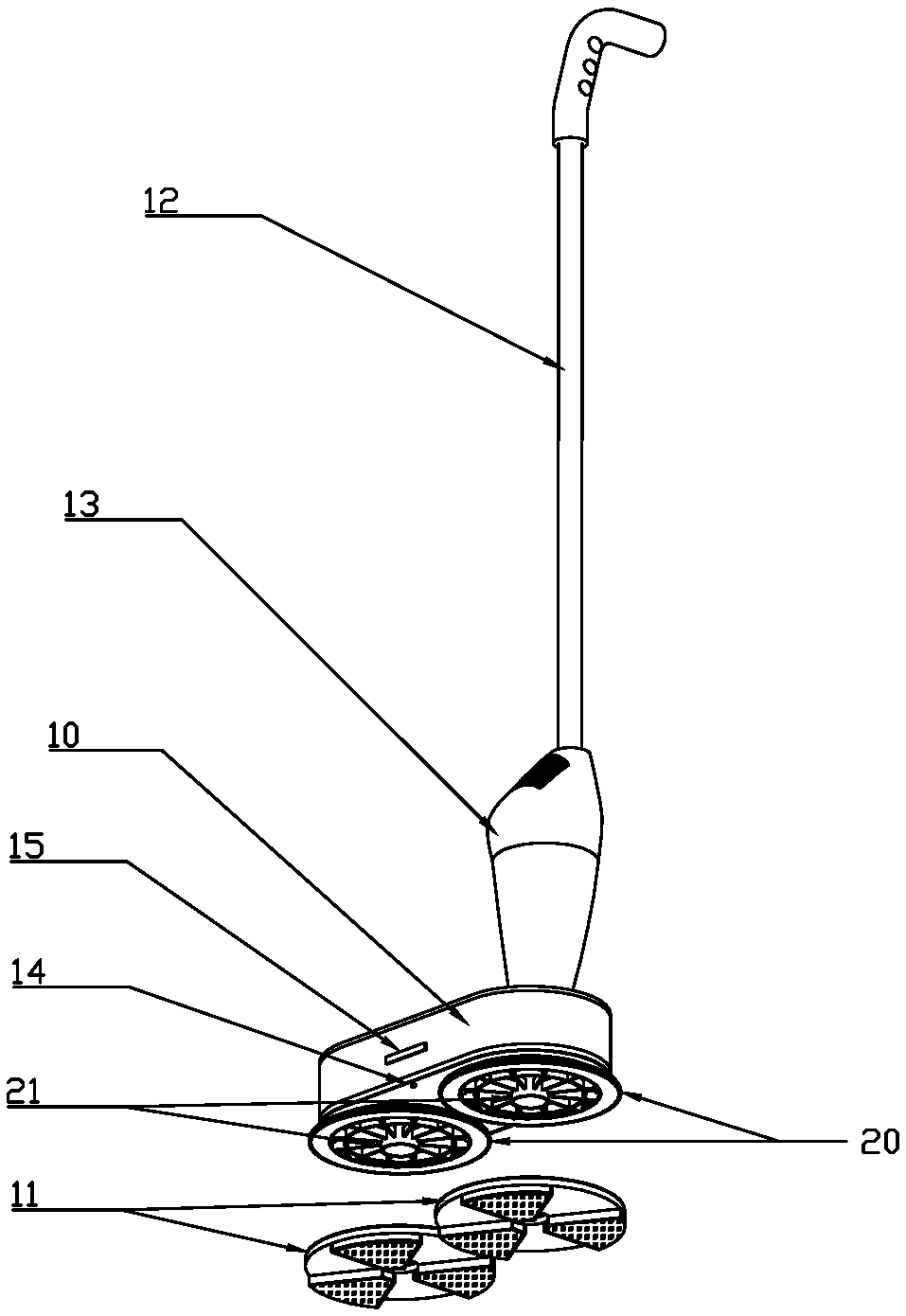
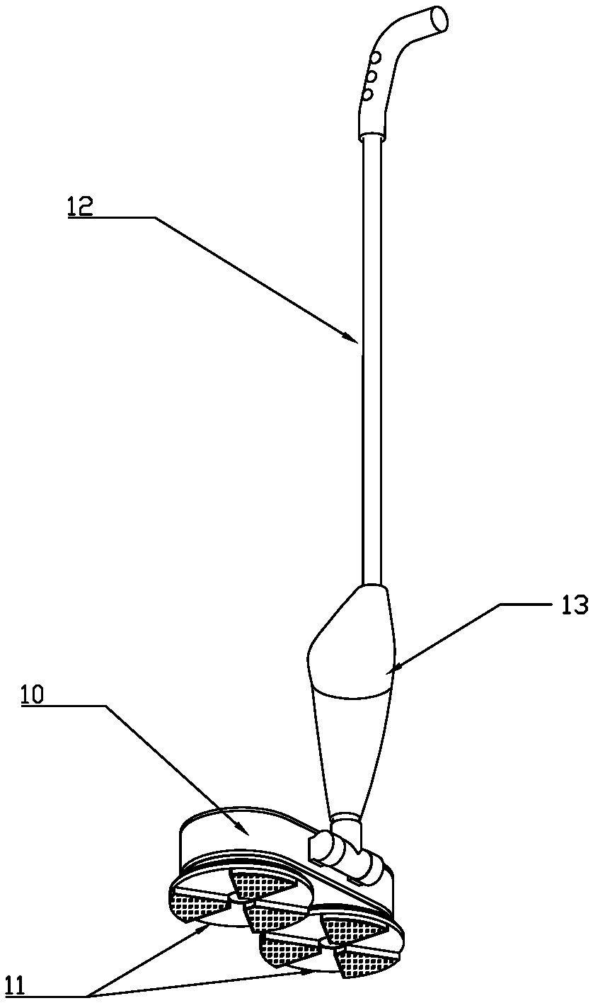
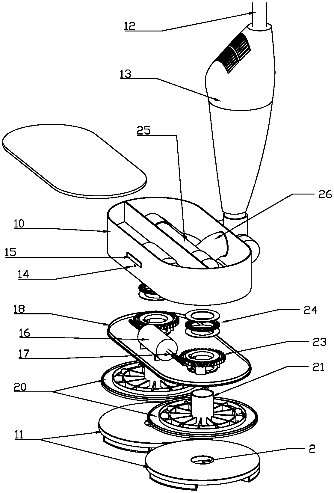
[0024] Such as figure 1 , figure 2 , image 3 , Figure 4 As shown, a preferred embodiment of the present invention comprises a host 10, a mop bar 12 rotatably connected to the host 10, a dust suction device 13 arranged on the mop bar 12, and the mop bar 12 connects with the main machine through the lower end of the dust suction device 13. 10 is hinged, and the air inlet pipe 26 connected to the lower end of the dust suction device 13 enters the interior of the host 10 and communicates with the middle part of the tee pipe 25. Two mounting plates 20 with opposite rotation directions are arranged below the host, and the center position of the mounting plate 20 is A hollow central shaft 21 is provided. The upper end of the central shaft 21 passes through the bottom shell 18 and enters the interior of the main engine 10. The two ends ...


PUM


Abstract

The invention discloses a multifunctional electric rotary mop. The multifunctional electric rotary mop comprises a main engine, a dust sucking device and two mounting discs, wherein the two mounting discs are arranged under the main engine and are opposite in rotation directions; a hollow center shaft is arranged at the center of each mounting disc; a detachable cleaning head is arranged under each mounting disc; each cleaning head comprises an upper cover; a dust sucking hole matched with each center shaft is arranged at the center of each upper cover; a plurality of cleaning bodies which extend radially and are raised downwards are arranged at intervals under each upper cover along a circumferential direction by taking the dust sucking hole as the center; the cleaning bodies are made offlexible wiping material; the lower surfaces of the cleaning bodies are in contact with a cleaned surface so as to wipe the cleaned surface through a rotating manner; a dust sucking air channel used for sucking dirt in each dust sucking hole is formed by a space among two adjacent cleaning bodies, each upper cover and the cleaned surface. The multifunctional electric rotary mop has the integratedfunctions of sweeping, mopping and sucking, can save time and labor, and is excellent in cleaning effect.

Description

technical field [0001] The invention relates to the field of cleaning tools, in particular to a multifunctional electric rotary mop. Background technique [0002] In the prior art, the electric rotary mop that uses the cleaning head rotation method to clean has been widely used. Taking the common electric rotary mop in the market as an example, the cleaning head usually uses one or two round mops, which are installed in the body. The motor drives the rotation to wipe the floor. However, due to the limited usable area of ​​the mop, and it can only be cleaned by rotating and rubbing the bottom plane, it cannot collect the dirt together like an ordinary mop, so the mop is easy to get dirty and needs to be cleaned frequently. Take off the mop for replacement and cleaning; in addition, because the motor is constantly rotating, the dirt will be scattered during the mopping process, so when using this type of electric rotary mop, the ground must be cleaned first, or cleaned with a ...

Claims


Application Information

Patent Timeline
IPC IPC(8): A47L11/30A47L11/40A47L13/20
CPCA47L11/30A47L11/4094A47L13/20
Inventor 阳珉
Owner 阳珉
Why Eureka
Try Eureka