Fin type heat exchanger system having cleaning function and method

A finned heat exchanger, cleaning technology, applied in the direction of cleaning heat transfer devices, lighting and heating equipment, flushing, etc., can solve the problems of affecting heat exchange efficiency, dirty blockage, difficult cleaning, etc., and achieve high cleaning efficiency and low energy consumption Low, thorough cleaning effect

Active Publication Date: 2018-09-25
NANJING KULANG ELECTRONICS
View PDF5 Cites 3 Cited by
  • Summary
  • Abstract
  • Description
  • Claims
  • Application Information

AI Technical Summary

Problems solved by technology

[0005] The problem of the prior art is: because the air contains dust, particles, sundries, etc., especially in the case of forced ventilation, dust, grains, sundries, etc. are easily adsorbed on the heat exchange tubes or fins of the fin heat exchanger. Above, it will cause fouling and blockage, which will affect the heat exchange efficiency
Existing cleaning methods include manual flushing with high-pressure water or high-pressure air, which is not only inefficient, wastes resources, and is difficult to clean thoroughly; because the fins are tightly arranged and light in texture, improper operation will cause fin deformation or damage. effect

Method used


Image

  • Fin type heat exchanger system having cleaning function and method
  • Fin type heat exchanger system having cleaning function and method
  • Fin type heat exchanger system having cleaning function and method

Examples


Embodiment 1

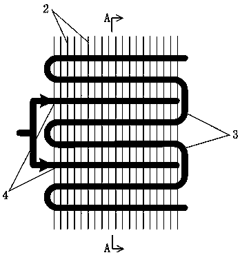
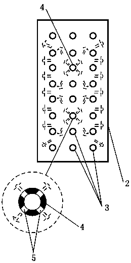
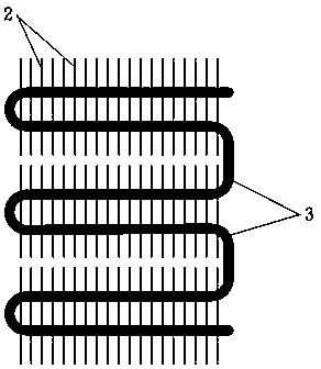
[0031] Usually, when the finned heat exchanger 1 is manufactured, the heat exchange tubes 3 are arranged uniformly and connected and fixed to the fins 2 . When adopting the technical solution of the present invention, in the process of assembling the fins 2 and the heat exchange tubes 3, several vacancies are reserved when the heat exchange tubes 3 are arranged (such as figure 2 shown), and then set the auxiliary pipe 4 in these vacancies (such as figure 1 shown). Through such a design, the auxiliary pipe 4 can be added to the finned heat exchanger 1 without increasing the difficulty of manufacturing the heat exchanger, and integrated with the original structure, passing through the hole 5 on the auxiliary pipe 4 Cleans from the inside out.

[0032] The structure of the hole 5 on the auxiliary pipe 4 is divided into two types:

[0033] Firstly, each hole 5 corresponds to a section of air flow channel formed by adjacent fins 2, so that the auxiliary medium acts on each fin ...

Embodiment 2

[0038] In this embodiment, the cleaning medium conveying device 8 is a piston cylinder, which at least includes a piston 8a, a piston cylinder 8b, and a piston motion control device 8c;

[0039] First, the cleaning medium input interface 7 is opened, the cleaning medium output interface 9 is closed, and the piston 8a is controlled by the piston motion control device 8c to move in reverse to suck the cleaning medium into the piston cylinder 8b; then the cleaning medium input interface 7 is closed, and the cleaning medium output interface 9 Open, the piston 8a is controlled by the piston motion control device 8c to move forward to push the cleaning medium into the auxiliary pipe 4, and then output through the hole 5; then, reciprocate according to this process;

[0040] Wherein, the movement speed of the piston 8a is adjusted by the piston motion control device 8c so as to realize the adjustment of the delivery speed of the cleaning medium; the movement distance of the piston 8a ...


PUM


Abstract

A fin type heat exchanger system having a cleaning function comprises a fin type heat exchanger (1), wherein the fin type heat exchanger (1) comprises, at least, fins (2) and heat exchange tubes (3).The fin type heat exchanger system is characterized in that one or more auxiliary tubes (4) for inputting a cleaning medium are arranged in the fin type heat exchanger (1), the auxiliary tubes (4) penetrate into and are plugged and distributed among the heat exchange tubes (3), and a plurality holes (5) are formed in tube walls of the auxiliary tubes (4). When the cleaning medium is input into theauxiliary tubes (4), the cleaning medium acts on the fins (2) and heat exchange tubes (3) around the holes (5) through output of the holes (5) and is gradually diffused from the fin type heat exchanger (1) from inside to outside so as to conduct deep cleaning on the fin type heat exchanger from inside to outside.

Description

technical field [0001] The present invention relates to a finned heat exchanger system and method with cleaning function, in particular to a system and a method for deep cleaning the finned heat exchanger from the inside to the outside by setting auxiliary pipes inside the finned heat exchanger and The method belongs to the technical field of design and manufacture of a heat exchanger system. Background technique [0002] Existing fin heat exchangers include at least fins and heat exchange tubes. Fin heat exchangers are usually composed of multiple sets of densely arranged heat exchange tube sections. The fins are closely arranged and the gaps are small; the working principle is The heat exchange function is realized by the heat exchange working medium circulating inside the heat exchange tube cluster and the gas outside the heat exchange tube cluster; the function of the fins is to increase the heat exchange area and enhance the heat exchange effect. There are two ways of ...

Claims


Application Information

Patent Timeline
Patent Type & Authority Applications(China)
IPC IPC(8): F28G9/00
CPCF28G9/00
Inventor 朱杰
Owner NANJING KULANG ELECTRONICS
Why Eureka
Try Eureka