Unmanned aerial vehicle (UAV) control system and method

A control system and unmanned aerial vehicle technology, applied in the field of unmanned aerial vehicle systems, can solve the control distance, automatic charging, cluster mode restrictions on large-scale operations of multi-rotor UAVs, control distance limitations of multi-rotor UAV systems, and inability to Effectively exploit advantages and other issues to achieve the effect of simplifying UAV flight control, improving product fault tolerance, and liberating UAV operation

Pending Publication Date: 2018-09-25
TIANJIN AEROSPACE ZHONGWEI DATA SYST TECH CO LTD
View PDF0 Cites 35 Cited by
  • Summary
  • Abstract
  • Description
  • Claims
  • Application Information

AI Technical Summary

Problems solved by technology

However, the existing product application mode is generally a single system, requiring operators to carry out system deployment, power-on, inspection, flight, withdrawal and other operations on site, so that it is impossible to realize the batch laying of UAV systems
[0003] At present, the control systems of multi-rotor UAVs on the market have the following deficiencies: (1) It is mainly a single-action control system, and the operation requires 1 to 2 people. In addition, although some products support the cluster function, they can be controlled by 1 to 2 people. There are multiple drones, but relevant personnel are still required to maintain and guarantee multiple drones; (2) The control distance of the multi-rotor drone system is limited by the radio station and image transmission, and it is impossible to achieve long-distance control operations; ( 3) Complicated manual intervention is required, including battery replacement, magnetic calibration, storage, unfolding and other operations with low operating efficiency; (4) Remote control is required, and the equipment is complicated to operate, requiring professional control, and the learning cost is high; ( 5) At present, the multi-rotor UAV system still needs to fly back to the take-off point, and its operating radius is still limited, and its advantages have not been fully utilized
[0004] The control distance, automatic charging, and cluster mode of multi-rotor UAVs are still difficult problems that limit the large-scale operation of multi-rotor UAVs, and their advantages cannot be effectively utilized

Method used


Image

  • Unmanned aerial vehicle (UAV) control system and method
  • Unmanned aerial vehicle (UAV) control system and method
  • Unmanned aerial vehicle (UAV) control system and method

Examples


Embodiment Construction

[0042] It should be noted that, in the case of no conflict, the embodiments of the present invention and the features in the embodiments can be combined with each other.

[0043] In describing the present invention, it should be understood that the terms "center", "longitudinal", "transverse", "upper", "lower", "front", "rear", "left", "right", " The orientations or positional relationships indicated by "vertical", "horizontal", "top", "bottom", "inner" and "outer" are based on the orientations or positional relationships shown in the drawings, and are only for the convenience of describing the present invention and Simplified descriptions, rather than indicating or implying that the device or element referred to must have a particular orientation, be constructed and operate in a particular orientation, and thus should not be construed as limiting the invention. In addition, the terms "first", "second", etc. are used for descriptive purposes only, and should not be understood ...


PUM


Abstract

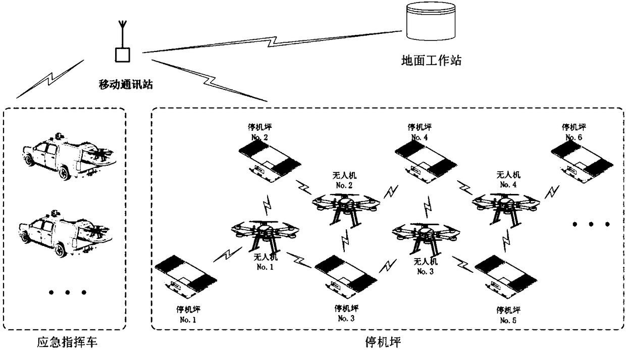
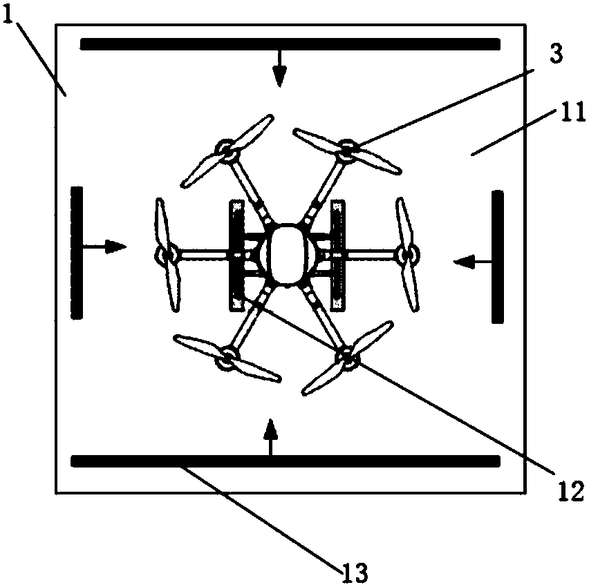
The invention provides a UAV control system and method. The system is characterized by comprising a multi-rotor UAV, an intelligent airplane parking area, a mobile communication station and a ground work station, the ground work station is in communication connection with the intelligent airplane parking area and the multi-rotor UAV via the mobile communication station, and the multi-rotor UAV isin communication connection with the intelligent airplane parking area. The intelligent airplane parking area solves the problem of folding/unfolding of the UAV in the launching and landing process, the UAV needs not to be unfolded or collected, a landing position can be provided for the multi-rotor UAV by point selection, and the problem in the working radius of the UAV is solved.

Description

technical field [0001] The invention relates to an unmanned aerial vehicle system, in particular to an unmanned aerial vehicle control system and an unmanned aerial vehicle control method. Background technique [0002] Nowadays, multi-rotor UAV products have poured into the civilian industry in large numbers, and they can monitor data in fixed areas by carrying different sensors. However, the existing product application mode is generally a single system, requiring operators to perform system deployment, power-on, inspection, flight, withdrawal and other operations on site, so that it is impossible to realize the batch laying of UAV systems. [0003] At present, the control systems of multi-rotor UAVs on the market have the following deficiencies: (1) It is mainly a single-action control system, and the operation requires 1 to 2 people. In addition, although some products support the cluster function, they can be controlled by 1 to 2 people. There are multiple drones, but r...

Claims


Application Information

Patent Timeline
Patent Type & Authority Applications(China)
IPC IPC(8): G05D1/10G01S19/42G05B19/04H04L29/08B64F1/00B60P3/11
CPCG05D1/101B60P3/11B64F1/00G01S19/42G05B19/04G05D1/104H04L67/125
Inventor 张勇宋飞宇郗小鹏张志军张冬赵坤张雪峰魏坤岭
Owner TIANJIN AEROSPACE ZHONGWEI DATA SYST TECH CO LTD
Why Eureka
Try Eureka