Optical fingerprint acquisition method, device and user terminal
A fingerprint collection and user terminal technology, applied in character and pattern recognition, instruments, computer components, etc., can solve the problems of reducing the accuracy of fingerprint collection, reducing the efficiency of fingerprint collection, and poor quality of fingerprint images
- Summary
- Abstract
- Description
- Claims
- Application Information
AI Technical Summary
Problems solved by technology
Method used
Image
Examples
Embodiment 1
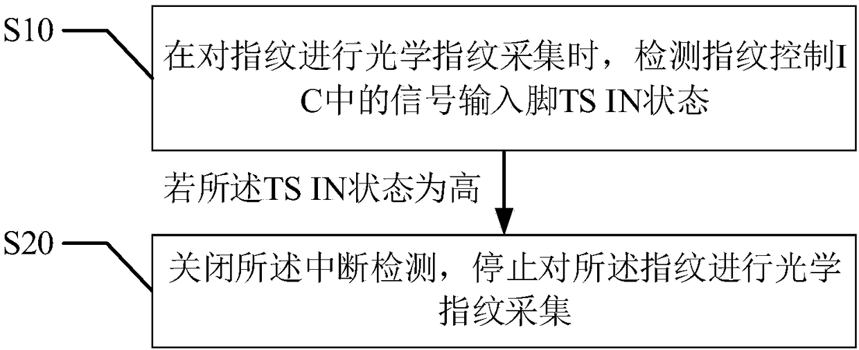
[0056] refer to figure 2 , the first embodiment of the present invention provides an optical fingerprint collection method, including:
[0057] Step S10, when performing optical fingerprint collection on the fingerprint, detecting the signal input pin TS IN state in the fingerprint control IC; the TS IN state includes high and low;
[0058] Step S20, if the state of the TS IN is high, disable the interrupt detection, and stop the optical fingerprint collection of the fingerprint.
[0059] As mentioned above, the fingerprint control IC is the fingerprint control integrated circuit.
[0060] As mentioned above, the signal input pin is a pin, also called a pin, and it is called a Pin in English. It is the connection between the internal circuit of the integrated circuit (chip) and the peripheral circuit, and all the pins constitute the interface of the chip. A section of the end of a lead that is soldered to form a solder joint with a pad on a printed board. Pins can be divi...
Embodiment 2
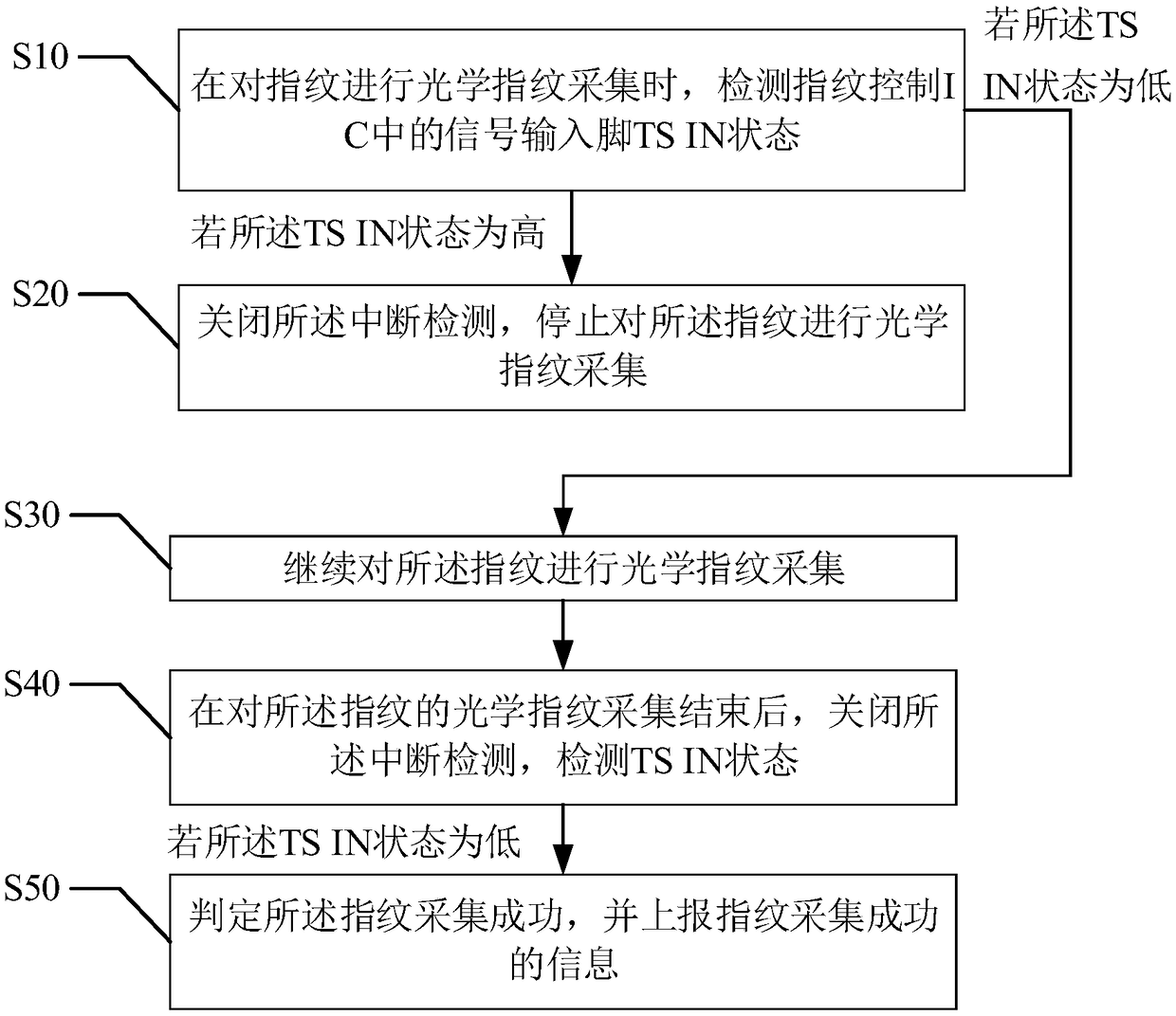
[0066] refer to image 3 , the second embodiment of the present invention provides an optical fingerprint collection method, based on the above figure 2 In the first embodiment shown, after the step S10 "when collecting optical fingerprints, enable interrupt detection and detect the TS IN state", it also includes:
[0067] Step S30, if the TS IN state is low, continue to perform optical fingerprint collection on the fingerprint.
[0068] As mentioned above, it is further judged whether the user's finger remains within the fingerprint collection range during the fingerprint collection process through the high and low state of TS IN. When the state of TS IN is low, it is determined that the current user's finger is still in the fingerprint collection state state, still within the fingerprint collection range, and the finger has not left, and the optical fingerprint collection can continue.
[0069] Step S40, after the optical fingerprint collection of the fingerprint is compl...
Embodiment 3
[0074] refer to Figure 4 , the third embodiment of the present invention provides an optical fingerprint collection method, based on the above figure 2 In the second embodiment shown, after the step S40 "after the optical fingerprint collection of the fingerprint is completed, close the interrupt detection and detect the TSIN state", it also includes:
[0075] In step S60, if the TS IN state is high, it is determined that the fingerprint collection fails, and the information of the fingerprint collection failure is reported.
[0076] As mentioned above, after the fingerprint collection is completed, judge whether the fingerprint collection is successful again through the state of TS IN, the fingerprint control IC turns off the interrupt detection, and detects the TS IN state. Report failure message. As mentioned above, the reported failure message can be sending information about collection failure to the CPU, which is then processed by the CPU, or it can be sending prompt...
PUM
 Abstract
Description
Claims
Application Information
 - R&D
- Intellectual Property
- Life Sciences
- Materials
- Tech Scout
- Unparalleled Data Quality
- Higher Quality Content
- 60% Fewer Hallucinations
Browse by: Latest US Patents, China's latest patents, Technical Efficacy Thesaurus, Application Domain, Technology Topic, Popular Technical Reports.
© 2025 PatSnap. All rights reserved.Legal|Privacy policy|Modern Slavery Act Transparency Statement|Sitemap|About US| Contact US: help@patsnap.com


