Agricultural mechanical tent

A technology for agricultural machinery and tents, which is applied in application, multi-fluid ratio control, poultry cages or houses, etc., can solve the problems of labor-intensive, time-consuming and labor-intensive, and can't open the shed film first, so as to improve work efficiency and save labor. Effect

Inactive Publication Date: 2018-09-28
罗龙霞
View PDF2 Cites 6 Cited by
  • Summary
  • Abstract
  • Description
  • Claims
  • Application Information

AI Technical Summary

Problems solved by technology

[0003] The application number is CN201520168368.9 patent, which is an open-close greenhouse structure for rice seedlings suitable for mechanized transplanting. Although it can make the mechanical transplanting seedlings rise and put the seedlings on the transplanter, the roots will not be broken, and the mechanical transplanting does not lack holes. Continuously ridges to ensure one-time transplanting and preservation of seedlings, but it does not have automatic functions and requires a lot of manpower
[0004] The application number is CN201720751115.3, which is a kind of greenhouse suitable for mechanized operations. Although the width of the shed door can be adjusted, the width of the shed door can be narrowed when people come in and out, so as to reduce the cold air from entering the shed. When the agricultural machinery enters and exits, the opening width of the shed door is widened so that the agricultural machinery can enter the greenhouse smoothly, but it cannot be easily and quickly opened the shed film to ventilate the greenhouse, and there is no automatic cover film Function, time-consuming and labor-intensive, and the device does not have the function of real-time detection of carbon dioxide concentration, farmers cannot grasp the carbon dioxide concentration of greenhouses in time, affecting crop yields

Method used


Image

  • Agricultural mechanical tent
  • Agricultural mechanical tent

Examples


Embodiment Construction

[0024] Below in conjunction with accompanying drawing, technical scheme of the present invention is described in further detail:

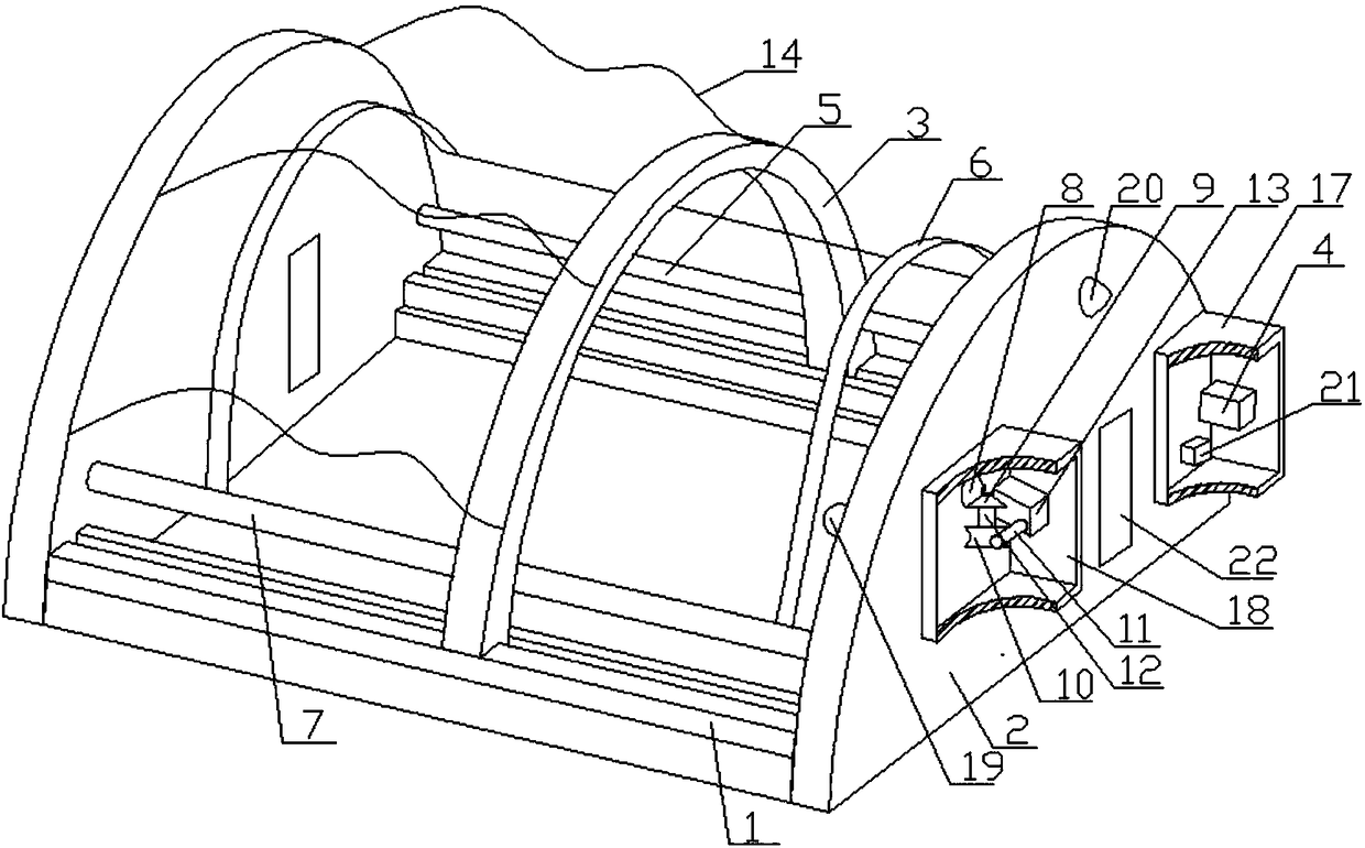
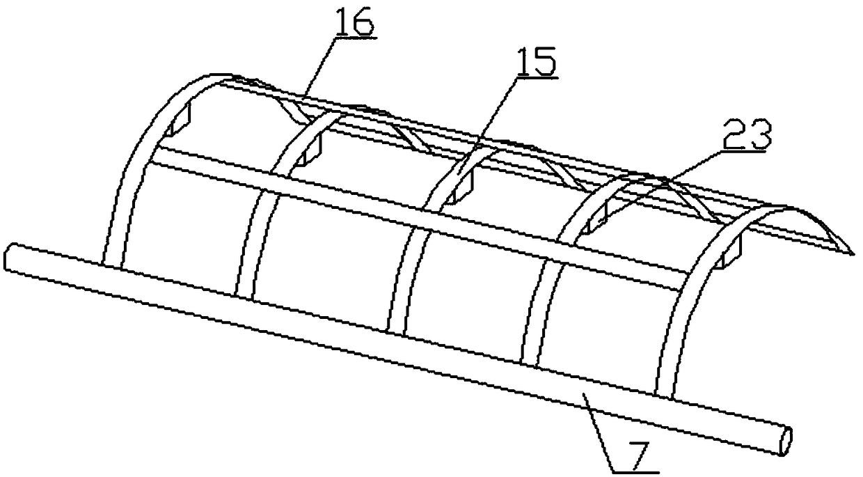
[0025] like figure 1 and figure 2 As shown, an agricultural machinery tent includes a slide rail 1, a support plate 2, a moving frame 3, a motor I4, a ball screw 5, a turret 6, a rotating shaft 7, a bevel gear I8, a bevel gear II9, a turbine 10, and a worm 11 , gear shaft 12, motor II 13 and film 14; the support plate 2 has two and is arranged in parallel, and the support plate 2 is a semicircular structure, and the frame is fixedly connected between the two support plates 2, and the frame is connected to the two A rectangular area is enclosed between the support plates 2; the slide rails 1 have two and are respectively fixedly connected to the frame on both sides of the support plate 2, the mobile frame 3 is a semicircular support, and the two sides of the mobile frame 3 The bottom ends are respectively slidably connected to the two slide rails...


PUM


Abstract

The invention discloses an agricultural mechanical tent. The agricultural mechanical tent comprises sliding rails, supporting boards, a moving rack, a motor I, a ball screw, rotating racks, a rotatingshaft, a bevel gear I, a bevel gear II, a turbine, a worm, a gear shaft, a motor II and a thin film. By means of the agricultural mechanical tent, an automatic film covering function is achieved, labor is greatly saved, the working efficiency is improved, when a device is in use, the motor II is started first, the worm and the shaft of the motor II rotates simultaneously, the worm is in transmission with the turbine in a meshed mode, the turbine and the bevel gear II rotate simultaneously, the bevel gear I is in transmission with the bevel gear II in a meshed mode, thus through the rotating shaft, the rotating racks rotate at a certain angle until the bottom ends of the other sides of the rotating racks are attached to a rack, then the motor I is started, the shaft of the motor I drives the ball screw to rotate and then drives the moving rack to move linearly from one supporting board to a position attached to the inner side of the other supporting board, and thus the thin film automatically covers the rotating racks; by means of the device, real-time monitoring the carbon dioxide concentration in a greenhouse and illumination are further achieved.

Description

technical field [0001] The invention relates to the field of modern agricultural machinery, in particular to an agricultural machinery tent. Background technique [0002] With the emergence of high molecular polymers - polyvinyl chloride and polyethylene, plastic films are widely used in agriculture. In the early 1950s, Japan, European and American countries successfully applied greenhouse films to cover hotbeds, and then covered small sheds and greenhouses with good results. my country introduced polyvinyl chloride agricultural film in the autumn of 1955. It was first used to cover vegetables in small sheds in Beijing, and achieved the effect of early maturity and increased production. The greenhouse was originally a special equipment for vegetable production. With the development of production, the application of greenhouses has become more and more extensive. At present, greenhouses have been used for potted flower and cut flower cultivation; fruit tree production is us...

Claims


Application Information

Patent Timeline
Patent Type & Authority Applications(China)
IPC IPC(8): A01G9/14A01G9/22A01K1/00A01K31/00F21V33/00G05D11/13G08B21/18
CPCA01G9/14A01G9/22A01K1/00A01K1/0047A01K31/00F21V33/00G05D11/131G08B21/182Y02A40/25
Inventor 罗龙霞
Owner 罗龙霞
Why Eureka
Try Eureka