Multi-stage rotational flow separation and filtering device with opposite rotational flows and use method

A cyclone separation technology with opposite swirl directions, applied in separation methods, chemical instruments and methods, filtration and separation, etc., can solve the problem that the discharged substances cannot achieve environmental protection, energy saving, reduce the separation efficiency of the cyclone, and block the bottom flow pipe of the cyclone. and other problems, to achieve the effect of shortening the separation distance, reducing the flow speed, and enhancing the swirl torque.

Pending Publication Date: 2018-09-28
中冶华成(武汉)工程有限公司
View PDF4 Cites 8 Cited by
  • Summary
  • Abstract
  • Description
  • Claims
  • Application Information

AI Technical Summary

Problems solved by technology

[0005] Although the existing cyclone can realize solid-liquid separation, and can separate the particles in mud, sewage and crude oil to a certain extent, it can only perform preliminary separation, and the discharged substances can not meet the requirements of environmental protection and energy saving.
In addition, when the existing cyclone device with ordinary structure handles some viscous liquids suc

Method used


Image

  • Multi-stage rotational flow separation and filtering device with opposite rotational flows and use method
  • Multi-stage rotational flow separation and filtering device with opposite rotational flows and use method
  • Multi-stage rotational flow separation and filtering device with opposite rotational flows and use method

Examples


Embodiment Construction

[0046] In order to have a clearer understanding of the technical features, purposes and effects of the present invention, the present invention will be further described below in conjunction with the accompanying drawings.

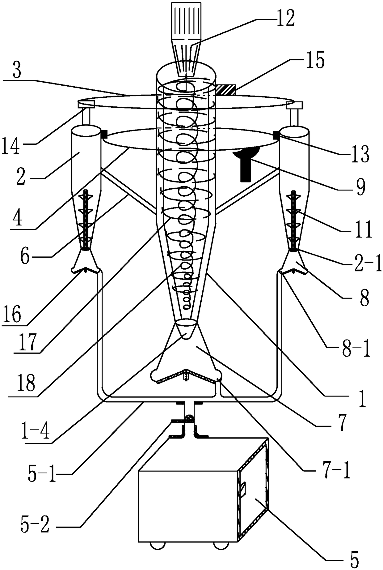
[0047] Such as figure 1 As shown, the device for multi-stage cyclone separation and filtration with opposite direction of rotation is characterized in that: the device includes a main cyclone separation drum 1, a primary separation and filtration device, an annular feed guide pipe 4 and an annular liquid outlet Guide pipe 3, the primary separation and filtering device includes at least two secondary cyclone separation cylinders 2, the plurality of secondary cyclone separation cylinders 2 are equidistantly distributed on the outer circumference of the main cyclone separation cylinder 1, each secondary cyclone separation The cylinder body of the cylinder 2 is fixedly connected with the cylinder body of the main cyclone separation cylinder 1 through the suppo...


PUM


Abstract

The invention provides a multi-stage rotational flow separation and filtering device with opposite rotational flows and a use method. The device comprises a main rotational flow separation cylinder, at least two secondary rotational flow separation cylinders, an annular feeding guide tube and an annular effluent guide tube, wherein feeding holes of multiple secondary rotational flow separation cylinders are serially connected with a solid-liquid mixture inlet through the annular feeding guide tube; the liquid outlet of each secondary rotational flow separation cylinder is communicated with thefeeding hole of the main rotational flow separation cylinder through the annular effluent guide tube. When the device is used, a solid-liquid mixture flows into the secondary rotational flow separation cylinders from top to bottom through the annular feeding guide tube, primary granule separation and filtration are carried out, the solid-liquid mixture is further fed into the main rotational flowseparation cylinder through the annular effluent guide tube under the action of rotational flows, secondary granule separation and filtration are carried out, and third separation and filtration arefinally carried out through a liquid discharge hole in the top of the main rotational flow separation cylinder. The device is capable of rapidly and effectively separating solid granules from the solid-liquid mixture, is simple and convenient to operate, and is capable of effectively lowering solid-liquid processing and production cost.

Description

technical field [0001] The invention relates to the technical field of solid-liquid two-phase separation, in particular to a multi-stage cyclone separation and filtration device with opposite rotation and a use method for separating particles from solid and liquid. Background technique [0002] The country is vigorously promoting the whole society to save energy, improve energy utilization efficiency, protect and improve the environment, and promote comprehensive, coordinated and sustainable economic and social development. However, in many industries at present, the treatment of some emissions cannot meet the requirements. For example, in the construction industry, especially in the construction of underground projects, there are a lot of mud and particles that are discharged without meticulous separation and filtration; In the process of sewage treatment, centralized collection, graded sedimentation and additive treatment are mainly adopted at present; in addition, in the ...

Claims


Application Information

Patent Timeline
IPC IPC(8): B01D36/04
CPCB01D36/006B01D36/045
Inventor 刘富均刘国清高珺余坤明孙志威柳文涛李召才汤宁斌
Owner 中冶华成(武汉)工程有限公司
Why Eureka
Try Eureka