

Bending die
A technology of bending dies and punches, applied in forming tools, manufacturing tools, metal processing equipment, etc., can solve problems such as difficult removal of copper bars, achieve the effects of ensuring product quality, reducing lateral deformation, and increasing safety
Inactive Publication Date: 2018-09-28
HENAN SENYUAN ELECTRIC CO LTD
View PDF10 Cites 5 Cited by
- Summary
- Abstract
- Description
- Claims
- Application Information
AI Technical Summary
Problems solved by technology
[0004] The purpose of the present invention is to provide a bending die to solve the problem in the prior art that the copper bar is difficult to take out from the mold after the mold bends the copper bar
Method used
View moreImage
Smart ImageViewing Examples

Examples
specific Embodiment 4
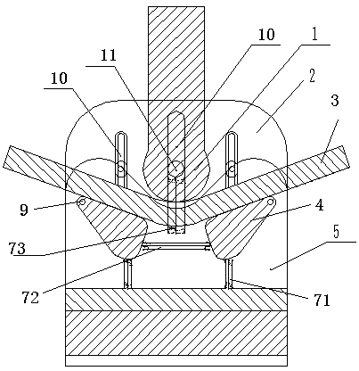
[0040] In specific embodiment 4 of the present invention, the structure of the bending die in this embodiment differs from the bending die in the above embodiment only in that guide plates are provided on both sides of the die to connect the first guide surface and the second guide surface. The surfaces are respectively arranged on the two guides of the guide plate towards the die.
Login to View More PUM
 Abstract
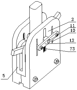
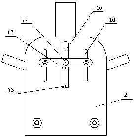
The invention relates to a bending die. The bending die comprises a male die body and a female die body. Supporting shafts which are used for supporting and bending a copper bar and matched with the male die body are arranged on the female die body. A first guide face for preventing the side wall of the copper bar from deforming and a second guide face corresponding to the first guide face are arranged on the female die body. An ejecting mechanism for ejecting the copper bar from the portion between the first guide face and the second guide face is arranged between the first guide face and thesecond guide face. The ejecting mechanism comprises swinging arms which are arranged on the supporting shafts in a sleeving manner and can rotate around the supporting shafts. According to the die, the groove matched with the copper bar for positioning is formed in the female die body. When the copper bar is bent, the first guide face and the second guide face can support the side wall of the copper bar, longitudinal bending and deformation of the copper bar are reduced effectively, and the copper bar is ejected upwardly through the ejecting mechanism after the copper bar is bent, so that thecopper bar can be formed at a time, the production efficiency is improved, the quality of products is guaranteed, and the safety is improved as well.
Description
technical field [0001] The invention relates to a bending die. Background technique [0002] Copper bars are very important in electrical equipment. During the installation of electrical equipment, copper bars often encounter connection problems. Because copper bars not only conduct electricity, but also play a role in installation, the processing of copper bars is particularly important, especially copper bars. row of bending work. [0003] At present, copper bars are mostly bent by bending machines. The traditional vertical bending processing method is to manually bend copper bars on a bending machine with a hand-held copper bar. The existing copper bar bending mold has a simple structure, which is prone to bending deformation, or the copper bar is difficult to take out from the mold after bending the copper bar, which not only prolongs the production cycle, reduces production efficiency, but also improves product quality. not tall. Contents of the invention [0004] ...
Claims
Login to View More Application Information
Patent Timeline
 Patent Type & AuthorityApplications(China)
IPC IPC(8): B21D37/10B21D5/01B21D45/04
CPCB21D5/01B21D37/10B21D45/04
Inventor高源赵亚中
OwnerHENAN SENYUAN ELECTRIC CO LTD