
chip removal tool

A cutting tool and flute technology, which is applied to milling cutters, manufacturing tools, metal processing equipment, etc., can solve the problem of incomplete chip discharge, prevent chips from staying inside the workpiece, and maintain cutting performance

Active Publication Date: 2021-05-04
CHONGQING CHANGAN AUTOMOBILE CO LTD
View PDF13 Cites 0 Cited by
  • Summary
  • Abstract
  • Description
  • Claims
  • Application Information

AI Technical Summary

Problems solved by technology

[0003] The purpose of the present invention is to propose a chip removal tool to improve the problem of incomplete chip discharge of the existing chip removal tool

Method used


Image

  • chip removal tool
  • chip removal tool
  • chip removal tool

Examples


Embodiment Construction

[0019]The present invention will be further described below with reference to the accompanying drawings.

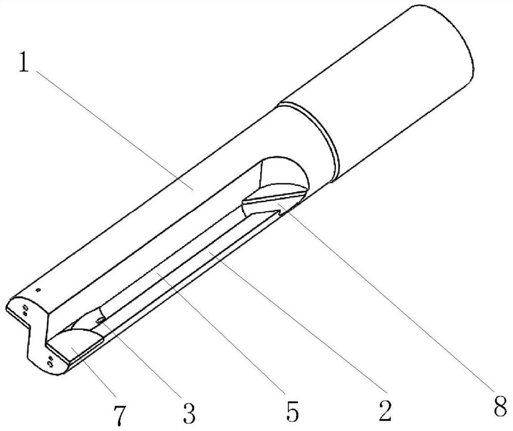
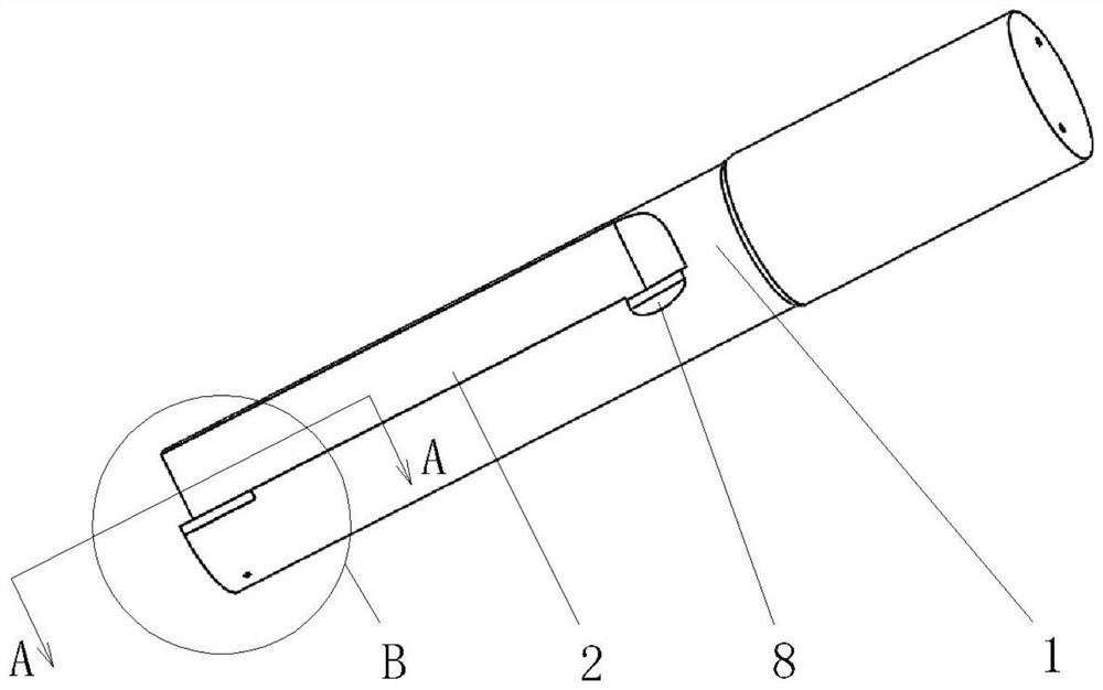
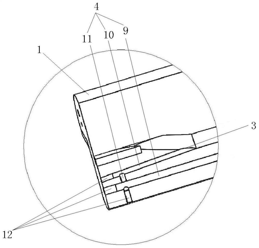
[0020]Such asfigure 1 withfigure 2 A chip cutting tool shown in the middle, including the columnar blade body 1, the front end of the columnar blade body 1 is provided with a cutting edge, and a tandem groove 2, a chip chip groove 2, a chip slot, a chip sloucher matches the cutting edge. 2 Self-cutting edges extend backward, characterized in that the chopper groove 2 is provided with a coolant outlet 3 towards the rearwardly rearward; the columnar blade body 1 is provided with a cooling liquid 4, the coolant outlet 3 and the cooling liquid 4 communicate . At the time of use, there is high-speed high-pressure coolant in the cooling liquid 4, which is advantageous to take away the heat generated during processing, the high pressure coolant is ejected from the coolant outlet 3; the front end of the columnar knife 1 The cutting edge is constantly cutting on the workpiece, and a large ...


PUM


Abstract

The invention relates to a chip removal tool, which comprises a columnar cutter body. The front end of the columnar cutter body is provided with a cutting edge, and the side wall of the columnar cutter body is provided with a chip removal groove matching the cutting edge. The extension is characterized in that a coolant outlet with an opening facing the rear is provided in the chip removal groove; a coolant channel is provided in the cylindrical cutter body, and the coolant outlet communicates with the coolant channel. The invention can effectively improve the problem of incomplete chip discharge of the existing chip removal tool.

Description

Technical field[0001]The present invention relates to the technical field of machining equipment, and more particularly to a tandem tool.Background technique[0002]The cylinder and cylinder head of the automobile engine cannot be avoided in the process, and it is inevitable that there will be chips into the waterway, the oil passage or camshaft chamber, in particular the cylinder head, and the camshaft chamber, which is complicated. It is difficult to completely clean and discharge. In order to ensure the cleanliness of the product, the chip structure needs to be used on the one hand, so that the chips is small as short as possible, avoiding the chip card to die in the waterway or the camshaxing chamber, causing the chip to be cleaned; on the other hand, the direction of processing is required The direction of the directional drag, making the chips into the water channels and camshaft chambers as possible to reduce the difficulty of the cleaning process. Usually chip cutting tools, s...

Claims


Application Information

Patent Timeline
Patent Type & Authority Patents(China)
IPC IPC(8): B23Q11/10B23C5/28
CPCB23C5/28B23Q11/10
Inventor 邓平任笑天刘俊吴钦德
Owner CHONGQING CHANGAN AUTOMOBILE CO LTD
Learn More