End mill including flat relief having reinforced rigidity

a flat relief and rigidity technology, applied in the field of end mills, can solve the problems of concave surface within a predetermined error range, and achieve the effect of excellent rigidity, excellent workability of a conventional flat relief, and excellent machinability and heat discharge performan

Inactive Publication Date: 2020-08-13
YG 1 CO LTD
View PDF0 Cites 0 Cited by
  • Summary
  • Abstract
  • Description
  • Claims
  • Application Information

AI Technical Summary

Benefits of technology

[0013]“The eccentric flat relief” is provided by repeatedly having a flat relief surface formed into a flat surface, and accordingly, has excellent workability of a conventional flat relief and maintains machinability and heat discharge performance more excellent than a conventional eccentric relief. On the other hand, the eccentric flat relief is arranged along the trajectory of the eccentric relief and has cutting tooth thicker than cutting tooth of the conventional flat relief. Accordingly, the eccentric flat relief is excellent in rigidity.

Problems solved by technology

Meanwhile, the flat relief is machined by a circular grinding wheel, so although a flat surface is machined by any large wheel, the flat surface may become a concave surface within a predetermined error range.

Method used


Image

  • End mill including flat relief having reinforced rigidity
  • End mill including flat relief having reinforced rigidity
  • End mill including flat relief having reinforced rigidity

Examples


Embodiment Construction

[0020]Hereinafter, the present invention will be described in more detail with reference to the accompanying drawings.

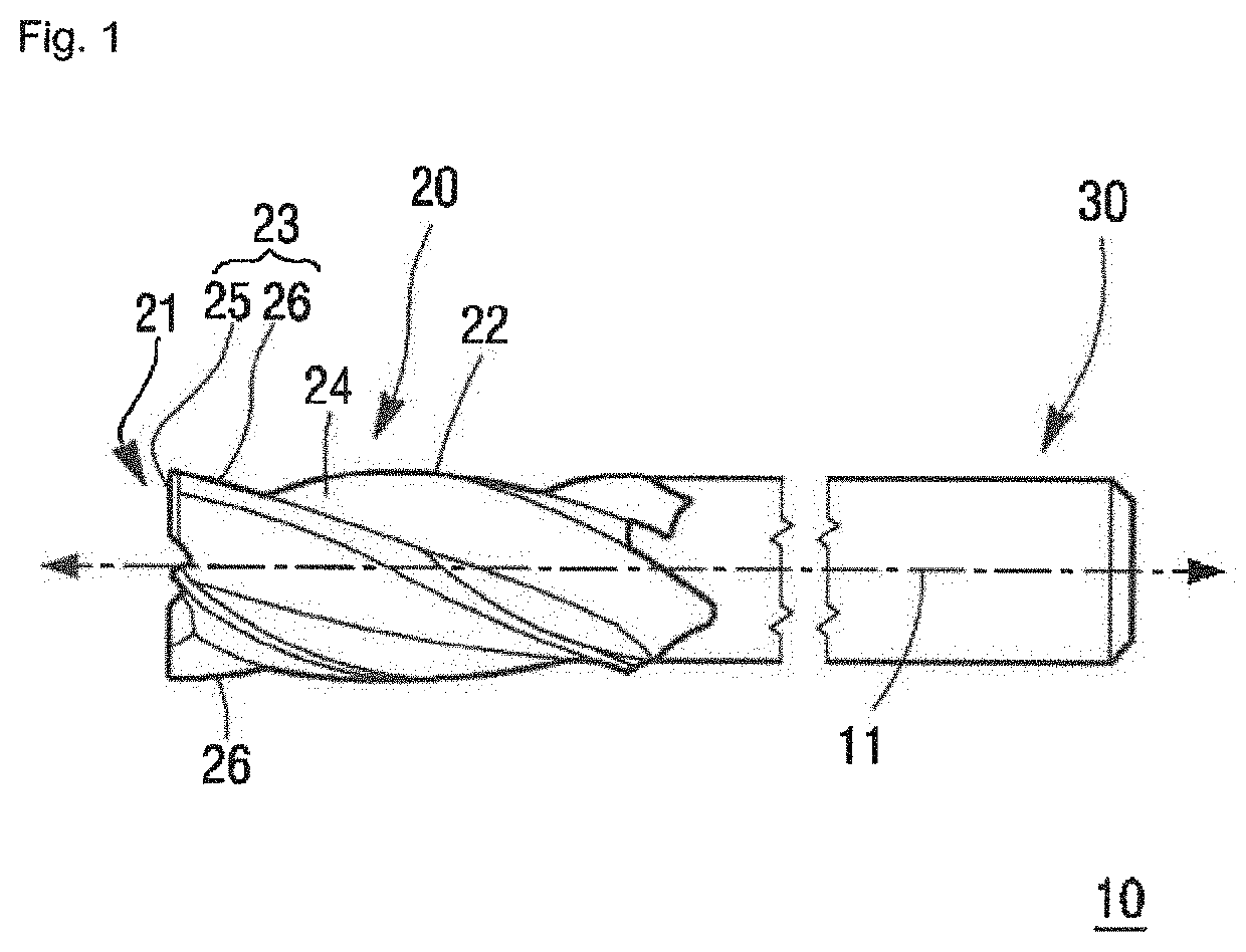
[0021]Referring to FIG. 1, an end mill according to the present invention 10 includes a cutting part 20 formed along a central axis 11 and a shank part 30 provided at a rear end of the cutting part 20. Although the end mill 10 of FIG. 1 is an end mill of a normal solid type, the end mill is not limited thereto and various types of end mills such as a dividing head type or a brazing type may be used.

[0022]As illustrated in FIG. 1, the end mill 10 is a square end mill, wherein a front end 21 of the cutting part 20 thereof is flat, but any conventional end mill may be used as the end mill. For example, the end mill of the present invention may be applied to a ball (Ball nose) type, a taper type, and a tapered ball type classified according to a front end of the cutting part 20. Furthermore, the shank part 30 may also be manufactured into any type shank of a straight sha...


PUM

PropertyMeasurementUnit
relief angleaaaaaaaaaa
cutting lengthaaaaaaaaaa

Abstract

An end mill having an eccentric flat relief formed thereon is proposed. The eccentric flat relief (simply referred to as “ELF”) includes at least three flat relief surfaces continuously arranged along a trajectory of an eccentric relief. Accordingly, the end mill, which combines strengths of the flat relief and an eccentric relief, has excellent rigidity and a heat discharge characteristic.

Description

CROSS REFERENCE TO RELATED APPLICATION[0001]The present application claims priority to Korean Patent Application No. 10-2019-0015213, filed Feb. 8, 2019, the entire contents of which is incorporated herein for all purposes by this reference.BACKGROUND OF THE INVENTIONField of the Invention[0002]The present invention relates to an end mill for machining a heat resistant alloy (based on titanium and nickel), wherein strengths of a flat relief and an eccentric relief are combined.Description of the Related Art[0003]An end mill as a rotary tool such as a drill includes a least one cutting part having cutting teeth machined along a tool axis and a shank part extending from the cutting part. The cutting part includes a plurality of cutting teeth and flutes alternately arranged from a front end thereof to a peripheral surface thereof. The end mill is a widely used tool for metal precision machining, wherein side blades (outer peripheral blades) thereof are used to cut the peripheral surfa...

Claims


Application Information

Patent Timeline
Patent Type & Authority Applications(United States)
IPC IPC(8): B23C5/10
CPCB23C2210/0407B23C2210/24B23C2210/54B23C5/10B23C2222/64B23C2222/88B23C5/28
Inventor PARK, YOUNG KOONKIM, HYUNG SUKLEE, SEUNG HYUN
Owner YG 1 CO LTD
Why Eureka
Try Eureka