
Comprehensive pipe gallery information system based on technology of Internet of Things

An Internet of Things technology and a technology of integrated pipe gallery, applied in the field of integrated pipe gallery, can solve the problems of difficult deployment and post-maintenance, large space occupation of the system, high cost, etc., to avoid information screening and conversion work, and to achieve high accuracy , the effect of simple structure

Inactive Publication Date: 2018-09-28
哈工大(张家口)工业技术研究院
View PDF10 Cites 6 Cited by
  • Summary
  • Abstract
  • Description
  • Claims
  • Application Information

AI Technical Summary

Problems solved by technology

With the rapid development of social informatization, some information technologies such as BIM and GIS have begun to be applied to the life cycle management of integrated utility corridors. The most basic level, and due to the own attributes of the pipe gallery and the special operation and maintenance environment, there are common problems in the existing technical solutions such as high cost, large system occupation space, and difficulties in deployment and post-maintenance

Method used


Image

  • Comprehensive pipe gallery information system based on technology of Internet of Things
  • Comprehensive pipe gallery information system based on technology of Internet of Things
  • Comprehensive pipe gallery information system based on technology of Internet of Things

Examples


Embodiment 1

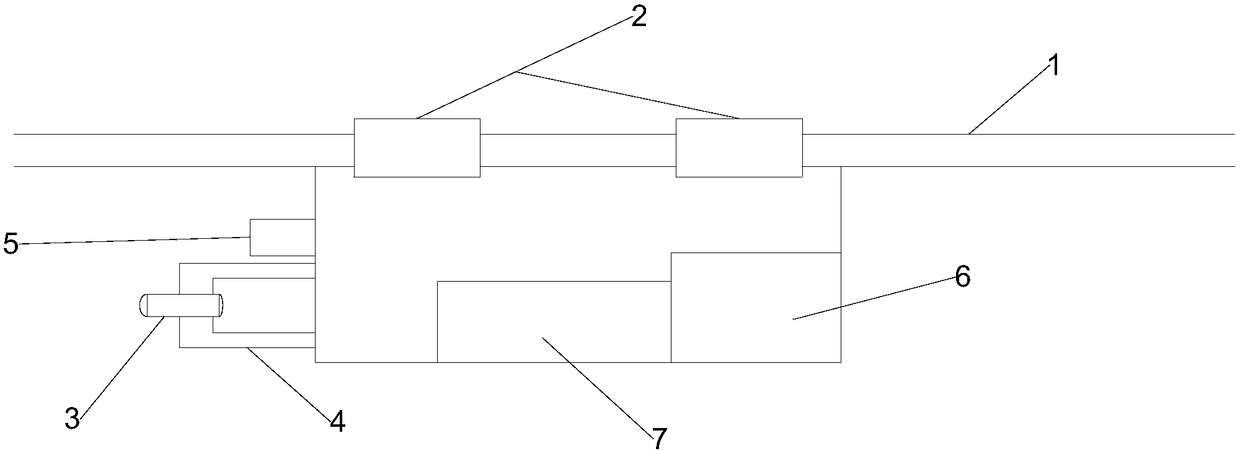
[0033] The invention provides a patrol robot, such as figure 1 As shown, the inspection robot includes a driving device 2, an acquisition device 3, a tracking device 5, an adjustment device 4 and a controller 6, and the driving device 2 includes a driving wheel suspended on the running rail 1 and is used to drive the The driving motor of the driving wheel; the acquisition device 3 is used to obtain the data information of the instruments and meters in the pipe gallery; the tracking device 5 is used to obtain the position information of the instruments and meters in the pipe gallery; the adjustment device 4 and the Acquisition connection for adjusting the position of the acquisition device 3; the controller 6 is respectively in communication with the drive device 2, the acquisition device 3, the tracking device 5 and the adjustment device 4, according to the The position information of the instrumentation obtained by the tracking device 5 is fed back to the controller 6, the co...

Embodiment 2

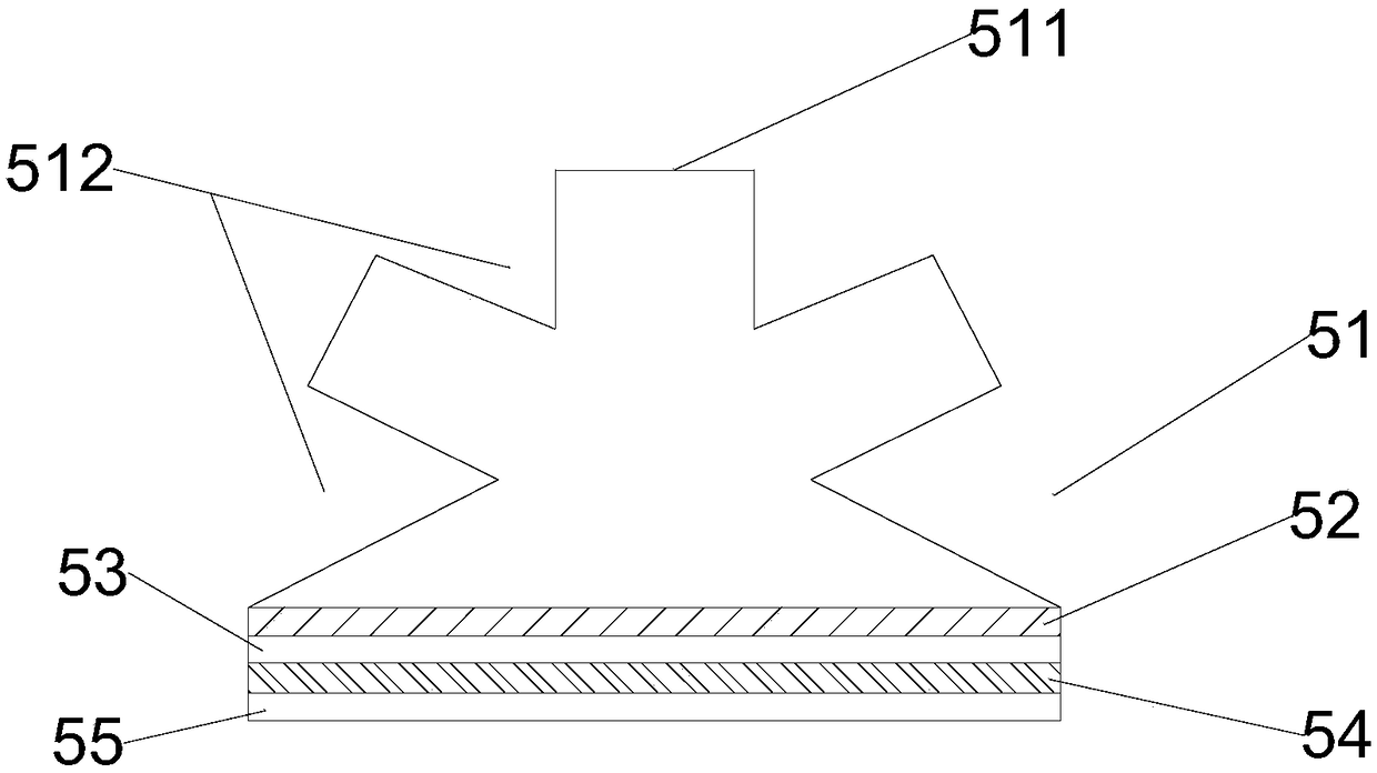
[0042] The difference between this embodiment and Embodiment 1 is that, as image 3 , 4 As shown, there are three light-guiding surfaces 511 on the refraction layer 51 in this embodiment, including a first light-guiding surface, a second light-guiding surface, and a third light-guiding surface, and the first light-guiding surface The light surface is located in the middle of the refraction layer 51, and the second light introduction surface and the third light introduction surface are respectively symmetrically distributed on both sides of the first light introduction surface. In this embodiment, the refraction layer 51 If it is set as an upwardly convex semicircular shape, the three light-guiding surfaces 511 are distributed in a semicircular shape on the refraction layer 51. The setting of the semicircular shape is conducive to fully collecting the light emitted by the specific light source on the instrument. light.

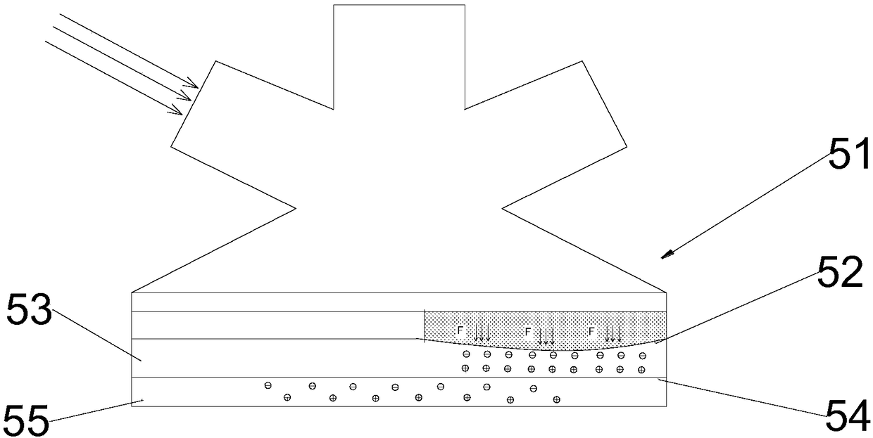
[0043] Such as image 3 As shown, the inspection robot...

Embodiment 3

[0048] Such as Figure 5 As shown, the difference between this embodiment and Embodiment 2 is that the refraction layer 51 in this embodiment is set in a semicircular shape concave downward, and the three light-guiding layers arranged on the refraction layer 51 The surface 511 forms a downwardly concave shape, so that the installation of the light-guiding surface 511 is firstly simpler and firmer, and since the refraction layer 51 is concave downward, it is easier to place the light-guiding surface 511 on its concave surface , and the light guiding surface 511 is more stable when placed on the concave surface, and secondly, the light guiding surface 511 is enclosed in the refractive layer 51, and the concave setting of the refractive layer 51 guides the light The surface 511 has a protective effect to a certain extent, and again can save material.


PUM


Abstract

The invention discloses a comprehensive pipe gallery information system based on the technology of Internet of Things. The comprehensive pipe gallery information system comprises a patrol system, a monitoring system and a master control terminal, the monitoring system and the patrol system are in communication connection with the master control terminal, the monitoring system conducts fixed-pointmonitoring and control on the interior of a pipe gallery based on the technology of Internet of Things, the patrol system conducts patrolling on the interior of the pipe gallery through a patrol robot, the patrol robot comprises a collecting device, a follow-up device, an adjusting device and a controller, the adjusting device is connected with the collecting device, and the controller is in communication connection with the collecting device, the follow-up device and the adjusting device. According to the system, the monitoring system and the patrol system are arranged inside the pipe galleryat the same time, the defects that during fixed-point monitoring, monitoring dead zones and dead angles exist or the constructing price is high are overcome, and the system is simple in allocation and low in maintaining cost.

Description

technical field [0001] The invention relates to the technical field of comprehensive pipe gallery, in particular to an information system of comprehensive pipe gallery based on Internet of Things technology. Background technique [0002] The underground comprehensive utility corridor plays an important role in improving the comprehensive carrying capacity of the city and meeting the basic needs of people's livelihood. The comprehensive pipe gallery management is a systematic and complex project. Because it is buried underground, it has the narrow and long linear characteristics of the urban macro level in terms of spatial form, and contains a variety of structures inside, and the information is unified in the process of design, construction and operation management. expression is more difficult. With the rapid development of social informatization, some information technologies such as BIM and GIS have begun to be applied to the life cycle management of integrated utility c...

Claims


Application Information

Patent Timeline
Patent Type & Authority Applications(China)
IPC IPC(8): B25J11/00G08C17/02H04L29/08
CPCB25J11/00G08C17/02H04L67/12
Inventor 于明李浩然张汉
Owner 哈工大(张家口)工业技术研究院
Learn More