Combined auto parts injection mold

A technology for auto parts and injection molds, which is applied in the field of combined auto parts injection molds, can solve the problems of defective injection parts, unclear edges and corners of injection parts, and large surface tension of molten materials, and achieves the effect of clear edges and corners.

Inactive Publication Date: 2018-09-28
CHONGQING YINSHENG MOLD
View PDF3 Cites 1 Cited by
  • Summary
  • Abstract
  • Description
  • Claims
  • Application Information

AI Technical Summary

Problems solved by technology

During injection molding, the raw materials used for injection molding are colloidal after being heated and melted, and most of the raw materials have poor fluidity after being heated and melted, and the surface tension of the molten material is also large, so the molten

Method used


Image

  • Combined auto parts injection mold
  • Combined auto parts injection mold

Examples


Embodiment Construction

[0019] The present invention will be described in further detail below by means of specific embodiments:

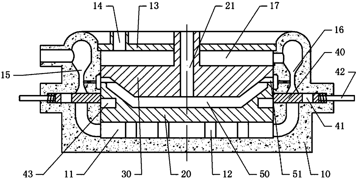
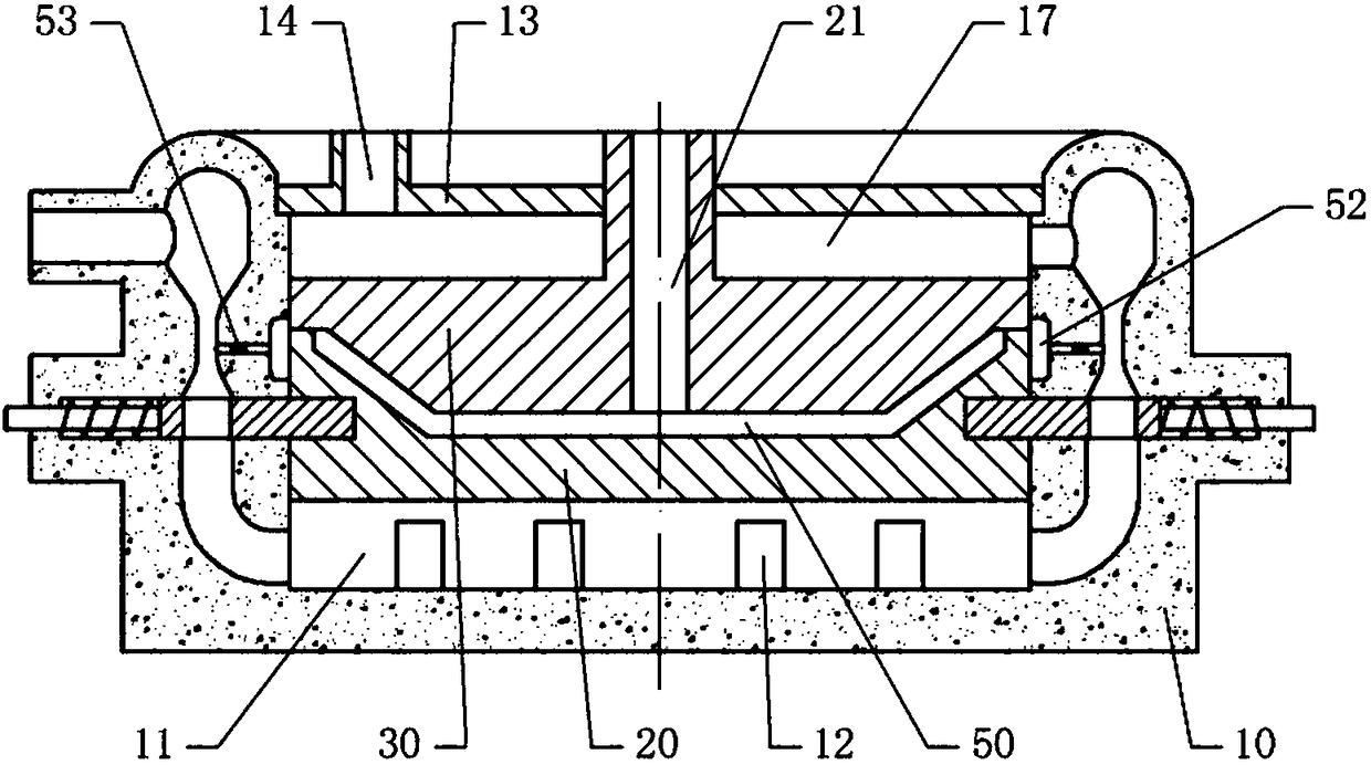
[0020] The reference signs in the drawings of the description include: seat body 10, boiling water tank 11, limit column 12, cover plate 13, water outlet 14, first channel 15, second channel 16, water chamber 17, concave mold 20, convex Die 30, spool 40, communication hole 41, pull rod 42, limit groove 43, mold cavity 50, surplus material gap 51, surplus material groove 52, one-way valve 53.

[0021] The embodiment is basically as figure 1 , figure 2 Shown:

[0022] The combined injection mold for auto parts in this embodiment includes a seat body 10, a male mold 30 and a concave mold 20, and the seat body 10 is made of heat-insulating ceramics. The seat body 10 is provided with a concave cavity, and the top of the cavity is open, and the punch 30 and the die 20 are put into the cavity from the opening on the top of the cavity, and the punch 30 and the die 20 are arra...


PUM


Abstract

The invention relates to an injection mold and specifically discloses a combined auto parts injection mold, which comprises a base equipped with a cavity. A male die and a female die are successivelyarranged from top to bottom inside the cavity. The bottom of the cavity is provided with a limited pillar. The sidewall of the base is provided with a location hole. By inserting a positioning pin into the location hole, the male die can be fixed in the cavity. A boiling water tank is arranged below the female die. Left and right sides of the female die are provided with valve cores which are slidingly connected to the base. The female die is equipped with spacing grooves for the valve cores being inserted therein. When the female die falls on the limited pillar, there is an excess material gap between the male die and the female die. When the valve cores are inserted in the spacing grooves, the male die and the female die cooperate to form an enclosed mold cavity. The top of the base is provided with a cover plate for sealing the cavity. A water chamber is arranged between the cover plate and the male die. The base is provided with a water inlet, and the cover plate is provided with awater outlet. When the valve cores are inserted in the spacing grooves, the water inlet, the water boiling tank, the water chamber and the water outlet are communicated. The mold of the invention ishelpful for letting plastic enter the narrow gap of the mold cavity so as to endow a workpiece with clear edges and corners.

Description

technical field [0001] The invention relates to an injection mold, in particular to a combined injection mold for auto parts. Background technique [0002] Injection mold is a tool for producing plastic products; it is also a tool for giving plastic products complete structure and precise dimensions. Injection molding is a processing method used in the mass production of certain complex-shaped parts. Specifically, it means that the heated and melted material is pressed into the mold cavity, and after being cooled and solidified, a molded product is obtained. During injection molding, the raw materials used for injection molding are colloidal after being heated and melted, and most of the raw materials have poor fluidity after being heated and melted, and the surface tension of the molten material is also large, so the molten material is not easy to enter the mold cavity. In some narrow grooves, the injection molded parts processed according to the current injection molding...

Claims


Application Information

Patent Timeline
IPC IPC(8): B29C45/26B29C45/73
CPCB29C45/0025B29C45/0046B29C45/26B29C45/2606B29C45/73
Inventor 邱建华
Owner CHONGQING YINSHENG MOLD
Why Eureka
Try Eureka