Rail-mounted new energy charging pile

A new energy, rail-type technology, applied in charging stations, electric vehicle charging technology, electric vehicles, etc., can solve the problems of inability to charge electric vehicles, limited battery life of charging equipment, poor flexibility, etc., to avoid inconvenience, prevent weathering and corrosion, The effect of flexible charging

Inactive Publication Date: 2018-09-28
深圳市中天协创科技发展有限公司
View PDF7 Cites 14 Cited by
  • Summary
  • Abstract
  • Description
  • Claims
  • Application Information

AI Technical Summary

Problems solved by technology

[0002] As a kind of clean energy, electric energy has been promoted by government departments in today's increasingly serious environmental pollution. With the strong support of national policies, more and more people choose to buy electric vehicles, but there are also a lot of problems that need to be solved One of the main problems is: at present, due to the limited battery life of charging equipment, frequent charging is required to supplement the power reserve of electrical equipment. The electric vehicle charging piles on the market are fixed on the wall or on the ground, installed in public buildings and In the parking lot or charging station of a residential area, but due to the limitation of the length of the charging cable, it is impossible to charge electric vehicles in other nearby parking spaces. The flexibility of the above-mentioned fixed charging piles is relatively poor, which is very inapplicable

Method used


Image

  • Rail-mounted new energy charging pile
  • Rail-mounted new energy charging pile
  • Rail-mounted new energy charging pile

Examples


specific Embodiment approach 1

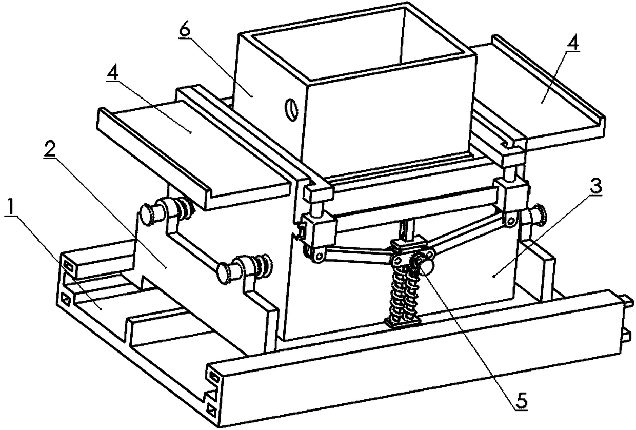
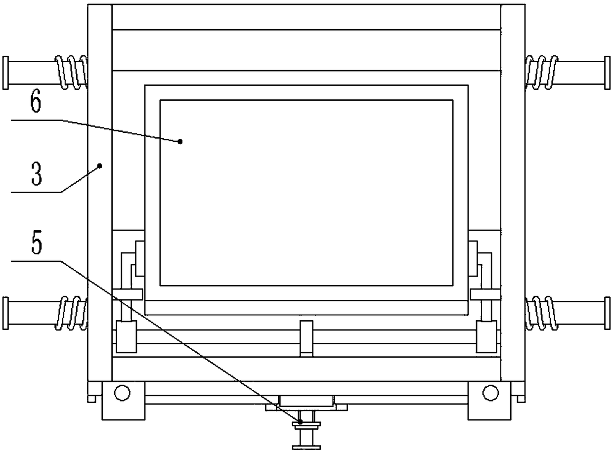
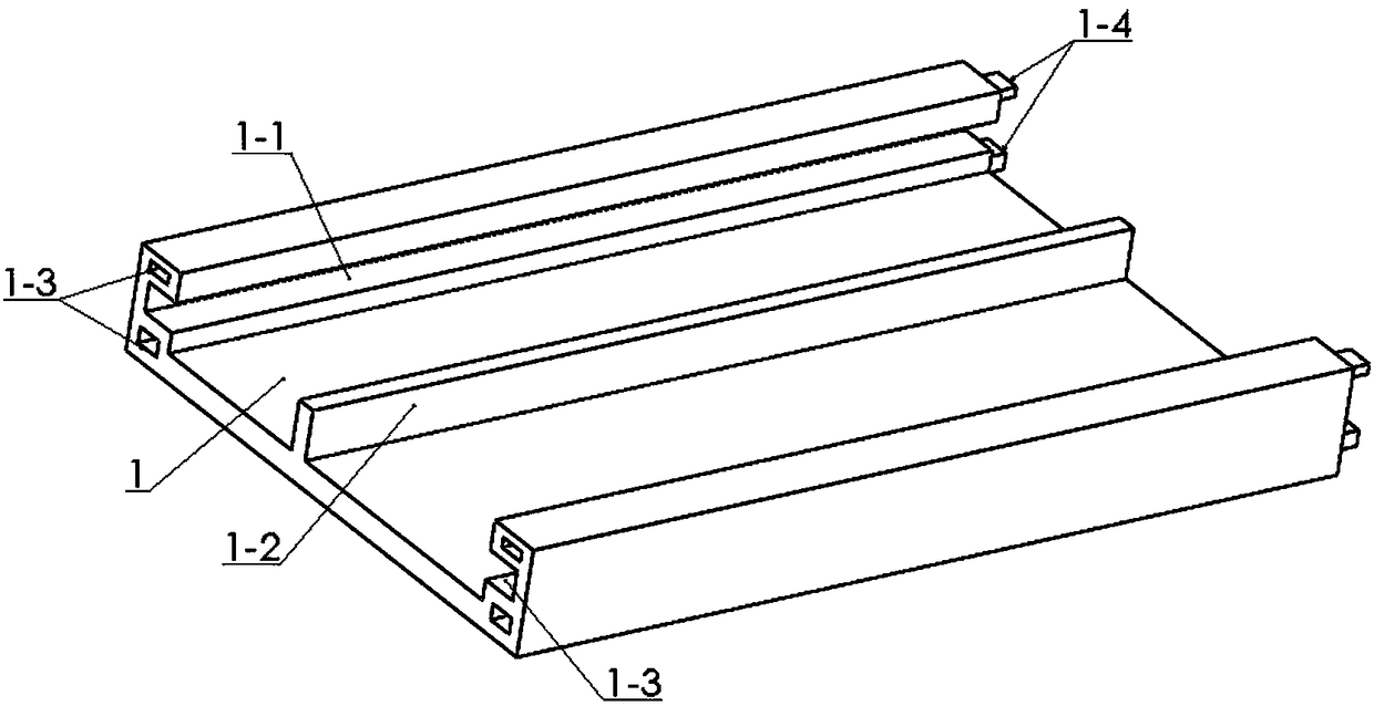
[0032] Combine below Figure 1-12To illustrate this embodiment, the present invention relates to the technical field of charging piles, more specifically, a track-type new energy charging pile, including a track 1, a sliding seat 2, a storage box 3, a dustproof cover 4, and a clip assembly 5 And the device box 6, the device can move the device box 6 to the top of the electric vehicle along the track, which is convenient for charging the electric vehicle, greatly avoiding the inconvenience caused by the inability to adjust the position of the device box 6 in time, and improving the charging pile. The utilization rate; the device has a buffer function to prevent the sliding seat 2 from colliding with other sliding seats 2 during the movement on the track 1 and damage the electrical components inside the device box 6; when not in use, the device box 6 can be stored in It is stored in the box body 3 to prevent potential safety hazards caused by weathering and corrosion of electric...


PUM


Abstract

The invention relates to the technical field of charging piles, in particular to a rail-mounted new energy charging pile. According to the rail-mounted new energy charging pile, a device box can movealong a rail to the position above an electric automobile, the electric automobile is conveniently charged, the inconvenience caused by the fact that the position of the device box cannot be adjustedin time is greatly avoided, and the use rate of the charging pile is increased. The charging pile has a buffering function, and the situation that a sliding seat collides with other sliding seats whenmoving on the rail and thus electric components in the device box are damaged is prevented. When not used, the device box can be stored in a containing box, the situation that the electric componentsin the device box are weathered and corroded or a short circuit accident happens due to the fact that the electric components are wetted by rainwater and thus potential safety hazards are generated is prevented, and therefore the charging pile charges the electric automobile more safely, economically and flexibly. Sliding ways are arranged on the rail, and the two sliding ways are symmetrically arranged at the front end and the rear end of the rail. Vertical seat boards are fixedly connected with the left end and the right end of the sliding seat, and sliding strips are fixedly connected withthe front end and the rear end of the sliding seat.

Description

technical field [0001] The invention relates to the technical field of charging piles, in particular to a track-type new energy charging pile. Background technique [0002] As a kind of clean energy, electric energy has been promoted by government departments in today's increasingly serious environmental pollution. With the strong support of national policies, more and more people choose to buy electric vehicles, but there are also a lot of problems that need to be solved One of the main problems is: at present, due to the limited battery life of charging equipment, frequent charging is required to supplement the power reserve of electrical equipment. The electric vehicle charging piles on the market are fixed on the wall or on the ground, installed in public buildings and In the parking lot or charging station of the residential area, but due to the limitation of the length of the charging cable, it is impossible to charge the electric vehicles in other nearby parking space...

Claims


Application Information

Patent Timeline
Patent Type & Authority Applications(China)
IPC IPC(8): B60L11/18
CPCB60L53/31B60L53/35Y02T10/70Y02T10/7072Y02T90/12
Inventor 布占贵
Owner 深圳市中天协创科技发展有限公司
Why Eureka
Try Eureka