
High-precision and high-stability mounting method for satellite-borne star sensor

A technology with high stability and installation method, which is applied in the direction of space navigation vehicle guidance device, aircraft, transportation and packaging, etc., can solve the problems such as the inability to effectively guarantee the accuracy and stability of the star sensor, and the accuracy and stability deviation, and achieve low implementation costs. , The effect of stable precision and simple method

Active Publication Date: 2018-09-28
SHANGHAI SATELLITE ENG INST
View PDF5 Cites 0 Cited by
  • Summary
  • Abstract
  • Description
  • Claims
  • Application Information

AI Technical Summary

Problems solved by technology

[0004] In the prior art, the star sensor is generally connected with the star structure by means of hexagonal socket head cap screws after accuracy measurement and then glued to prevent the accuracy deviation from occurring again after the star is installed. However, this method cannot effectively guarantee the accuracy of the star sensor. The precision stability of the rotational degree of freedom pointing around the optical axis (around the Z direction) before and after the mechanical test leads to deviations in precision stability. Therefore, how to ensure the deviation of precision stability from the perspective of assembly has become a difficult problem

Method used


Image

  • High-precision and high-stability mounting method for satellite-borne star sensor
  • High-precision and high-stability mounting method for satellite-borne star sensor
  • High-precision and high-stability mounting method for satellite-borne star sensor

Examples


Embodiment Construction

[0033] The present invention will be described in detail below in conjunction with specific embodiments. The following examples will help those skilled in the art to further understand the present invention, but do not limit the present invention in any form. It should be noted that those skilled in the art can make several modifications and improvements without departing from the concept of the present invention. These all belong to the protection scope of the present invention.

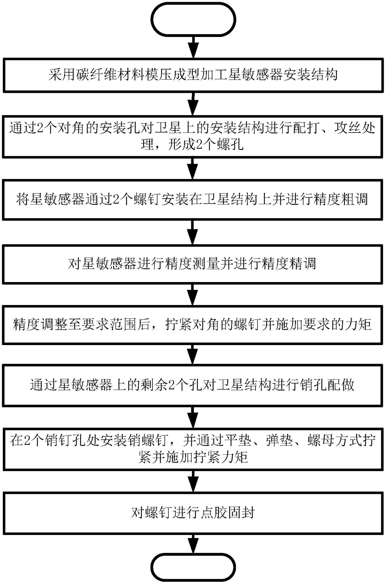
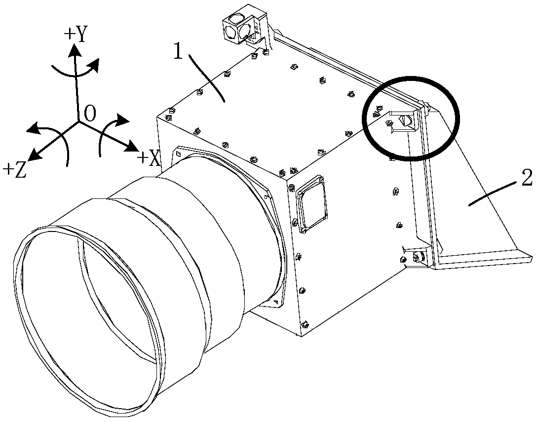
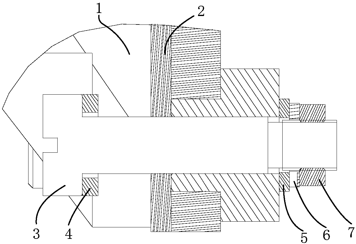
[0034] Such as Figure 1-Figure 3 As shown, the embodiment of the present invention provides a high-precision and high-stability installation method for a spaceborne star sensor, including the following steps:

[0035] S1. The installation structure of the star sensor is manufactured by molding carbon fiber material, and thread tapping is reserved at the corresponding position, that is, the interface embedded part for drilling;

[0036] S2. Matching and tapping the star sensor installation struct...


PUM


Abstract

The invention provides a high-precision and high-stability mounting method for a satellite-borne star sensor. The high-precision and high-stability mounting method comprises the following steps that acarbon fiber material is manufactured into a star sensor mounting structure through mould pressing machining, and thread tapping parts are reserved at the corresponding positions; the positions, corresponding to two diagonal mounting holes of an accurate measurement prism of the star sensor, of the star sensor mounting structure are matched and tapped to form two screw holes; the star sensor is mounted on a satellite structure through screws, and the precision is roughly adjusted; the precision of the star sensor is measured and finely adjusted; after the precision is adjusted to be within the required range, the diagonal screws are tightened, and required torque is applied; the satellite structure is subjected to pin hole matching through two remaining holes in the star sensor; pin screws are mounted at two pin holes and tightened through flat pads, elastic pads and nuts, and tightening torque is applied; and the screws and the pin screws are dispensed to be firmly sealed. When beingassembled, the satellite-borne star sensor can be mounted on a satellite through the existing mounting holes in the star sensor in high-precision and high-stability modes.

Description

technical field [0001] The invention relates to the overall design technology of a spacecraft, in particular to a high-precision and high-stability installation method for a spaceborne star sensor. Background technique [0002] With the development of advanced space technologies such as space remote sensing mapping and aerospace reconnaissance in China, star sensors, as an independent high-precision attitude measurement instrument, have become necessary attitude-sensitive components on satellites, space shuttles and space stations. Under the background that our country has realized the application of high-precision star sensors, it is of practical significance to study the high-precision and high-stability star mounting technology of high-precision star sensors to ensure the success of satellite in-orbit missions. [0003] With the whole star, the star sensor experiences vibration, temperature changes and other factors during launch and in-orbit operation, which cause the in...

Claims


Application Information

Patent Timeline
IPC IPC(8): B64G1/22B64G1/36
CPCB64G1/22B64G1/36
Inventor 陈汀吴远波陈重华
Owner SHANGHAI SATELLITE ENG INST
Learn More