
Eureka
For R&D, Eureka makes reading and utilizing patents & technical documents easy.
Eureka AIR
Designed for self-driven R&D workflows. Generate viable solutions, solve complex R&D challenges, empower your innovation with AI.

Eureka Materials
Designed for material experts only. Revolutionize your material R&D, from search, analyze, to developing new materials.

TechResearch
Generate reliable direction feasibility study reports for your R&D in just a few steps.

TechSeek
Discover and master advanced knowledge NOW. Basics, ideas, possibilities, all at once.

TechMind
As an expert in R&D Theories, TechMind can generates customized viable solutions instantly.

TechRisk
Analyze your overall solution with one click, know your potential R&D risks in advance.

TechMonitor
Get weekly tech updates, stay abreast of the latest tech innovations and key insights.
Multifunctional compactor for waterproof coil construction
A waterproofing membrane and compactor technology, which is applied in the processing of building materials, tools for roof engineering, roofing, etc., can solve the problems of wasting manpower, fatigue of personnel, and decline in quality control, so as to improve work efficiency, processing and manufacturing. Simple, fatigue-reducing effect
- Summary
- Abstract
- Description
- Claims
- Application Information
AI Technical Summary
Problems solved by technology
Method used
Image

Examples
Embodiment 1
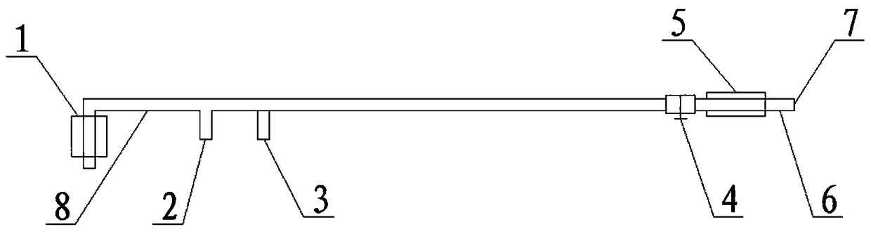
[0016] See figure 1 , Including a bracket 8 and a roller 1, the bracket 8 is a hollow structure for internal gas transmission, the roller 1 is arranged at the forefront of the bracket 8 for direct contact with the coil, the gas outlet ignition end 2 is located in the middle of the bracket 8, the coil The material side bracket 3 is fixed on the bracket 8 for lifting the coil. The gas inlet valve 4 is set at the rear end of the bracket 8 to control the ignition size of the gas and whether to enter and exit the gas. The handle 6 is set at the rear end of the bracket 8. A handle sheath 5 is fitted on the handle 6. The handle sheath 5 is used to increase the friction between the handle 6 and the hand to prevent slippage. The end of the bracket 8 is provided with a gas inlet 7 where a gas hose and a gas tank are used. Connected.
Embodiment 2
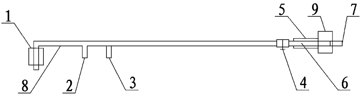
[0018] See figure 2 , The difference from Embodiment 1 is: an automatic hose reel 9 is also installed at the rear end of the bracket 8. The automatic hose reel 9 is used to automatically control the contraction of the gas hose, reducing the workload of organizing and collecting the gas hose and shortening The construction period improves work efficiency.
[0019] Instructions:
[0020] While pushing the carrying bracket 8 forward through the roller 1 manually, the coil side bracket 3 is fixed on the bracket 8 for lifting the coil material to be lifted by human control, and the gas outlet ignition end 2 is lifted with the coil side frame 3 to heat the coil material , The roller 1 automatically compacts the heated coil at the back. During the operation, the measuring instrument is used to lay out the position of the coil, and then the coil is laid flat, and the heated and compacted side of the coil is fixed on the side bracket 3 of the coil. , If you simply heat up, you can remove...
PUM
 Abstract
Description
Claims
Application Information
 - R&D Engineer
- R&D Manager
- IP Professional
- Industry Leading Data Capabilities
- Powerful AI technology
- Patent DNA Extraction
Browse by: Latest US Patents, China's latest patents, Technical Efficacy Thesaurus, Application Domain, Technology Topic, Popular Technical Reports.
© 2024 PatSnap. All rights reserved.Legal|Privacy policy|Modern Slavery Act Transparency Statement|Sitemap|About US| Contact US: help@patsnap.com