Hand-operated intelligent control lock

A technology of intelligent control and manual knob, which is applied in the field of locks, can solve problems such as the failure to open or close the door, the failure to rotate the lock body, and the functional defects of the electronic combination lock, etc., and achieve the effect of improving the intelligent performance

Pending Publication Date: 2018-09-28
沅陵县品诺鼎电子科技有限公司
View PDF0 Cites 4 Cited by
  • Summary
  • Abstract
  • Description
  • Claims
  • Application Information

AI Technical Summary

Problems solved by technology

[0003] At present, most traditional smart electronic locks use motor gearboxes. When the indoor manual knob is opened, there is a possibility that the shaft of the lock cylinder and the shaft of the gearbox cannot be engaged.
The principle of manual knob unlocking: Press the manual knob, so that the shaft of the motor gearbox is separated from the manual knob, and the manual knob directly turns the lock cylinder to achieve the purpose of opening the lock body, so as to open the door. After the indoor manual knob opens the door, when the motor works When the manual knob is pressed down, the shaft of the lock cylinder is separated from the shaft of the gearbox. The purpose of turning the lock body, at the same time, the purpose of opening or closing the door cannot be achieved, resulting in functional defects in the electronic combination lock, and at the same time lacking the security of the lock

Method used


Image

  • Hand-operated intelligent control lock
  • Hand-operated intelligent control lock
  • Hand-operated intelligent control lock

Examples


Embodiment Construction

[0026] The present invention will be described in further detail below in conjunction with the accompanying drawings.

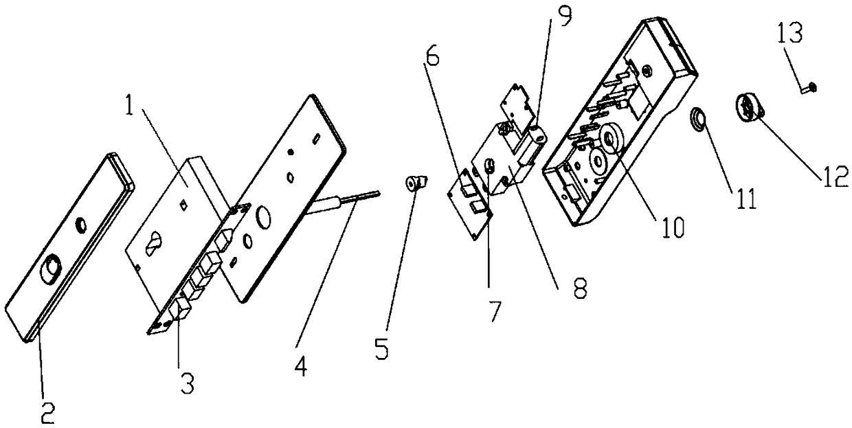
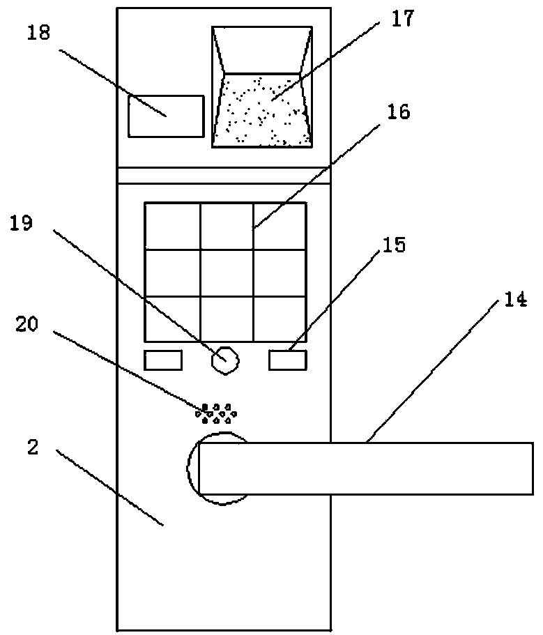
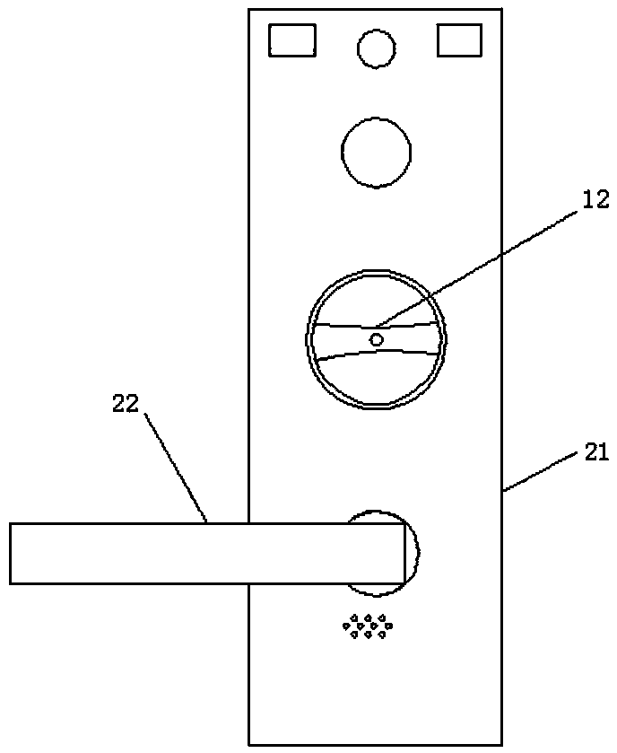
[0027] like Figure 1 to Figure 7 As shown, the specific embodiment of the present invention includes a lock cylinder 4 and a motor 9, the motor 9 is connected to the gearbox shaft 7, and the lock cylinder 4 is controlled by the door lock controller to rotate, the dead bolt 3 is telescopic to realize opening and closing the door, and the gearbox shaft The inner side of 7 is provided with a lock core clutch shaft 5, the lock core 4 is movably connected in the lock core shaft 5 holes, one end of the lock core shaft 5 is fixedly connected to the manual knob 12, the manual knob 12 and the spring 11 are installed on the spring base 10, and the manual knob Sensor is arranged in 12.

[0028] Further, two, three or four steps are provided on both sides of the front end of the lock core rotating shaft 5, which cooperate with the vertical grooves on both sides of the ...


PUM


Abstract

The invention relates to a hand-operated intelligent control lock. A motor is connected with a gearbox rotary shaft. An electronic control system controls a lock cylinder to rotate. A lock cylinder rotary shaft is arranged on the inner side of the gearbox rotary shaft. The lock cylinder is movably connected to the interior of a hole of the lock cylinder rotary shaft. One end of the lock cylinder rotary shaft is fixedly connected with a hand-operated rotary knob. The hand-operated rotary knob and a spring are mounted on a spring base. A magnet and a boss are arranged in the hand-operated rotaryknob. Hall elements or light touch inductive switches or reed switches of a PCB at the bottom of the spring base induce signals that a button is pressed. When the lock cylinder is rotated through theindoor hand-operated rotary knob and a lock body is unlocked completely, the electronic control system controls the lock cylinder rotary shaft to automatically rotate forwards or reversely to be aligned with vertical grooves for restoration; the gearbox rotary shaft of the motor and the lock cylinder rotary shaft are completely engaged and then stop automatically. The problem that a motor gearboxrotary shaft and a lock cylinder rotary shaft cannot be engaged in a hand-operated rotary knob unlocking mode is solved. Meanwhile, the functional state of automatic locking is restored. The hand-operated intelligent control lock is intelligent, safe and flexible.

Description

technical field [0001] The invention relates to the technical field of locks, in particular to a manual intelligent control lock. Background technique [0002] The existing electronic combination lock is an electronic product that controls the operation of a circuit or a chip (access control system) through a password input, thereby controlling the closing of a mechanical switch and completing the tasks of unlocking and locking. There are many types of it, ranging from simple circuit products to cost-effective products based on chips. Now the widely used electronic combination lock is based on the chip and realized by programming. In the field of security technology prevention, electronic locks with anti-theft alarm function replace traditional mechanical combination locks, which overcome the shortcomings of mechanical combination locks with few passwords and poor safety performance, and make combination locks more effective both in technology and in performance. Both have...

Claims


Application Information

Patent Timeline
Patent Type & Authority Applications(China)
IPC IPC(8): E05B47/00E05B17/22E05B15/04G07C9/00
CPCE05B47/0012E05B15/04E05B17/22E05B2015/0424G07C9/00563G07C9/00944
Inventor 李观春
Owner 沅陵县品诺鼎电子科技有限公司
Why Eureka
Try Eureka