
Combined-and-separated-type anti-theft window and special lock thereof

An anti-theft window and detachable technology, applied in the field of anti-theft windows, can solve the problems of unfavorable outdoor operation and escape, no fixing mechanism of the anti-theft grid, easy to pinch hands, etc., and achieve the effects of simple structure, convenient use and strong practicability.

Pending Publication Date: 2018-09-28
成都市臻晟工贸有限公司
View PDF7 Cites 2 Cited by
  • Summary
  • Abstract
  • Description
  • Claims
  • Application Information

AI Technical Summary

Problems solved by technology

For example, the anti-theft window is integrated, which is not conducive to outdoor work and escape; the anti-theft grid has no fixed mechanism, and it is easy to pinch hands, etc.

Method used


Image

  • Combined-and-separated-type anti-theft window and special lock thereof
  • Combined-and-separated-type anti-theft window and special lock thereof
  • Combined-and-separated-type anti-theft window and special lock thereof

Examples


Embodiment 1

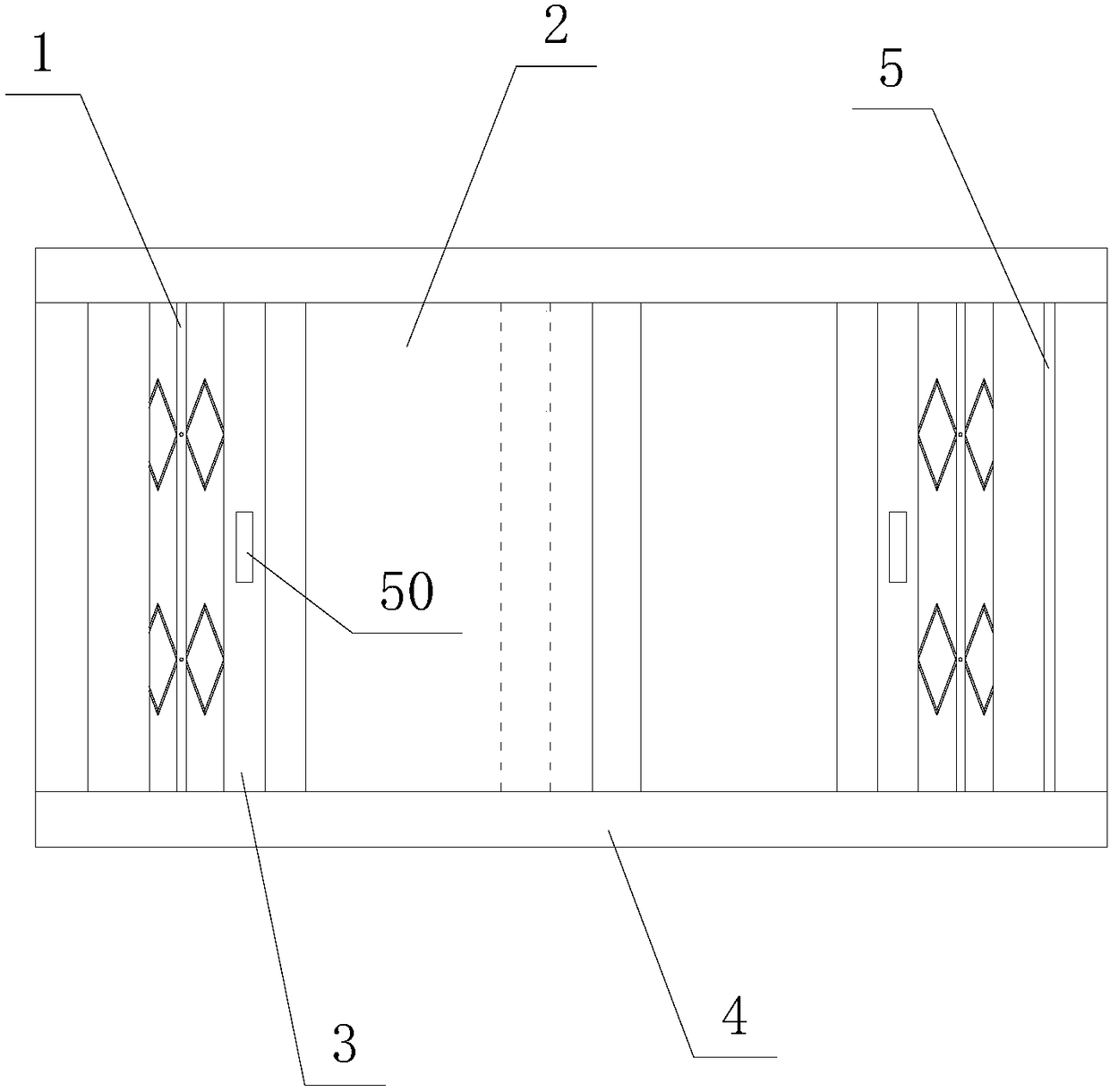
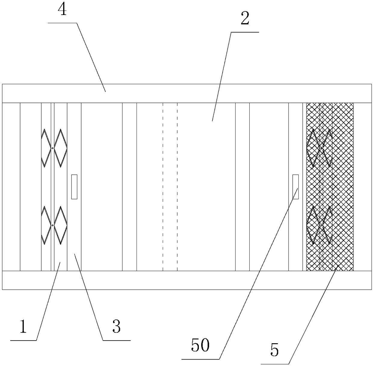
[0027] Such as Figure 1 to Figure 5 As shown, a combined and separated anti-theft window and its special lock, the present invention is an improvement and innovation based on the Chinese patent application number 201720625955.5, a rod and a hidden anti-theft window, which solves the problem of the original technology There are deficiencies.

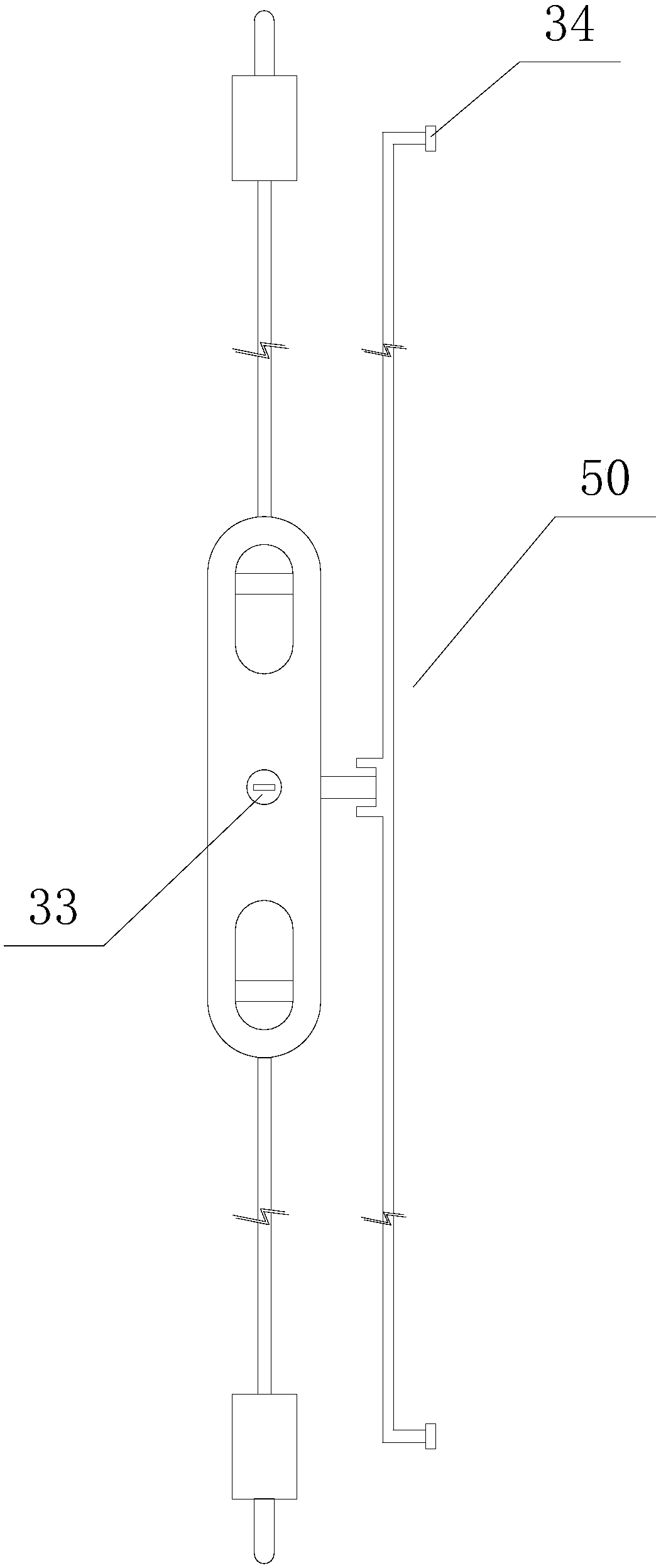
[0028] A combined and separated anti-theft window, comprising an anti-theft window body, a connecting part 3 is arranged between the anti-theft lattice 1 and the sash 2 of the anti-theft window body, and the connecting part 3 can preferably be made of an aluminum alloy profile, and the material is relatively light. The upper and lower ends of the connecting part 3 are slidingly fitted in the window frame 4 of the anti-theft window body. One end of the connecting part 3 is connected to the anti-theft grid 1, and the other end is connected to the frame of the window sash 2 through a special lock 50. The window frame 4 connected to the anti...

Embodiment 2

[0037] The difference between this embodiment and Embodiment 1 is that the spring positioning latch mechanism has another structural form, such as Image 6As shown, the spring 12 of the spring positioning latch mechanism is arranged on the back of the panel 20 , and the two ends of the spring 12 are respectively connected to the slider 16 . A baffle 19 is arranged inside the slide 21 , and the rod 15 passes through the baffle 19 to connect with the slider 16 , the rod 15 is directly connected to the latch 11 , and the latch 11 passes through the two ends of the connecting portion 3 and pushes against the window frame 4 . A stop ring 40 is arranged in the middle of the chute 21, and the stop ring 40 is used to pass through the spring 12 and limit the displacement distance. Its use process is the same as that of Embodiment 1. Use two fingers to move the slider 16 to the middle position. While the slider 16 compresses the spring 12, it drives the rod 15 to move to the middle, and...


PUM


Abstract

The invention discloses a combined-and-separated-type anti-theft window. The combined-and-separated-type anti-theft window comprises an anti-theft window body. A connecting part is arranged between ananti-theft grid of the anti-theft window body and a window sash, and the upper end and the lower end of the connecting part are slidably matched in a window frame of the anti-theft window body. One end of the connecting part is connected with the anti-theft grid, and the other end of the connecting part is connected to a frame of the window sash through a special lock. Concealing boxes are arranged on the window frame connected with the anti-theft grid and the connecting part correspondingly and used for concealing the anti-theft grid. The special lock is applied to the combined-and-separated-type anti-theft window and comprises a spring positioning plug pin mechanism and a key separating mechanism, the spring positioning plug pin mechanism acts on the anti-theft grid, and the key separating mechanism acts on the window sash. The structure is simple, design is reasonable, functionality is higher, using is convenient, the anti-theft window can be fixed randomly, hand clamping is prevented, and the problems of a traditional integrated anti-theft window are solved.

Description

technical field [0001] The invention belongs to the technical field of anti-theft windows, in particular to a combined and separated anti-theft window and its special lock. Background technique [0002] The Chinese patent application number 201720625955.5 is a rod and a hidden anti-theft window. Although it solves the problems of anti-theft and aesthetics, it also has many deficiencies and needs further improvement. For example, the anti-theft window is integrated, which is not conducive to outdoor work and escape; the anti-theft grid has no fixed mechanism, and it is easy to pinch hands. [0003] Therefore, how to overcome the above problems has become an urgent problem to be solved by those skilled in the art. Contents of the invention [0004] The object of the present invention is to provide a combined and separated anti-theft window and its special lock, which can completely solve the above-mentioned deficiencies in the prior art. [0005] The purpose of the present...

Claims


Application Information

Patent Timeline
Patent Type & Authority Applications(China)
IPC IPC(8): E06B9/06E06B9/54E06B3/46E05C9/00E05C9/04E05C17/02
CPCE05C9/006E05C9/04E05C9/041E05C17/02E06B3/4609E06B9/0607E06B9/54E06B2009/543E05Y2900/148
Inventor 周立勇
Owner 成都市臻晟工贸有限公司
Learn More