Light source structure wide in light outgoing face

A light-emitting surface and light source technology, applied in the field of LED lighting, can solve the problems of rigid and single structural design, glare, lack of novelty, etc.

Inactive Publication Date: 2018-09-28
李鹤荣
View PDF8 Cites 0 Cited by
  • Summary
  • Abstract
  • Description
  • Claims
  • Application Information

AI Technical Summary

Problems solved by technology

Existing LED lamps generally use a light source structure on the lamp panel as a lighting source. The light source structure generally includes a substrate and an LED chip arranged on the substrate. The LED chip is packaged on the substrate with fluorescent glue. In order to protect the LED chip, the traditional structure will On the fluorescent layer, a transparent waterproof adhesive layer is formed by a dispensing machine. Uneven distribution, narrow luminous range, small light emitting surface of LED light source structure, excessive concentration of light intensity distribution, causing light spots on the ground, and easy to generate glare to make people feel dizzy. Cover, the existing light-transmitting cover is integrally formed on the LED chip by an injection molding machine. Due to the limitation of the process, the lower end surface of the light-transmitting cover is closely attached to the LED chip. Although the light is dispersed to a certain extent, the light will still be compact and concentrated. At the center position, the light intensity around the center is relatively weak. If large-angle lighting is required, the number of light source structures can only be increased to meet the lighting requirements. Stiff and single, lack of novelty, it is difficult to meet the different requirements of different places and different users

Method used


Image

  • Light source structure wide in light outgoing face
  • Light source structure wide in light outgoing face
  • Light source structure wide in light outgoing face

Examples


Embodiment Construction

[0020] It should be understood that the specific embodiments described here are only used to explain the present invention, not to limit the present invention.

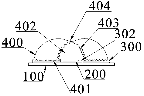
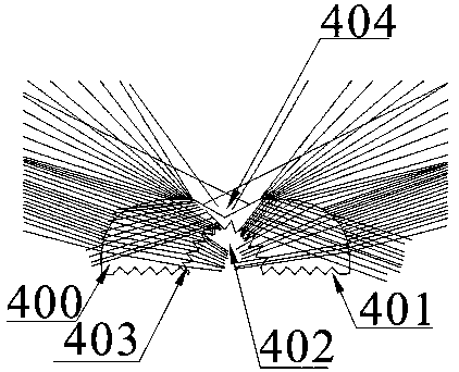
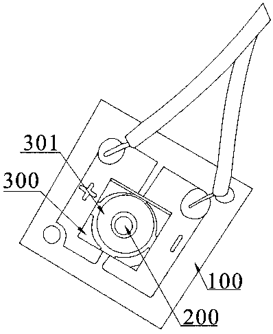
[0021] refer to Figure 1 to Figure 3 , an embodiment of a light source structure with a wide light-emitting surface of the present invention is proposed, which can be installed on a lamp for large-angle lighting, including a substrate 100, an LED chip 200 disposed on the substrate 100, and a fluorescent light covering the LED chip 200. Layer, the LED chip 200 is fixed on the substrate 100 through a bracket 300, and the bracket 300 is made of insulating material, which has good insulation performance and high safety performance. The bracket 300 is provided with a light source cavity 302 for accommodating the LED chip 200, and the LED chip 200 is encapsulated in the light source cavity 302 through a fluorescent layer. In this embodiment, the conductive pins led out from the LED chip 200 pass through the bracket 300 an...


PUM


Abstract

The invention discloses a light source structure wide in light outgoing face. The light source structure wide in light outgoing face can be installed on a lamp, and comprises a substrate, an LED chipand a fluorescent layer; the LED chip is fixed to the substrate through a support, and the support is provided with a light source cavity used for containing the LED chip, and is further provided withan annular groove; and the light source structure further comprises a light transmitting cover fixed to the annular groove and covering the LED chip. The lower end face of the light transmitting cover of the light source structure forms an empty cavity covering the LED chip, and the shape of the empty cavity is similar with that of a bullet head; meanwhile, the upper end face of the light transmitting cover is concavely provided with a recessed cavity in the shape of a reverse cone; due to the reasonable arrangement of the recessed cavity and the empty cavity, the light transmitting cover isarranged in a manner of a concave lens; after the light ray outwards irradiated at right angles by the LED chip is deflected through the concave lens, the light ray is diverged, a light beam becomes wide, and therefore the light ray becomes uniform and soft, the illuminating angle is increased, the light ray illuminating range is widened, the large-angle lighting requirement is met, and the lightsource structure wide in light outgoing face is economical and environment-friendly. The light source structure is reasonable in design and novel and unique in structure.

Description

technical field [0001] The invention relates to the technical field of LED lighting, in particular to a light source structure with a wide light emitting surface. Background technique [0002] Lamps are indispensable lighting appliances, and various lamps are widely distributed in various areas. With the improvement of people's living standards, the requirements for lamps are getting higher and higher, and LED lamps with advantages such as energy saving, environmental protection, and high light efficiency are gradually welcomed by consumers. Existing LED lamps generally use a light source structure on the lamp panel as a lighting source. The light source structure generally includes a substrate and an LED chip arranged on the substrate. The LED chip is packaged on the substrate with fluorescent glue. In order to protect the LED chip, the traditional structure will On the fluorescent layer, a transparent waterproof adhesive layer is formed by a dispensing machine. Uneven di...

Claims


Application Information

Patent Timeline
Patent Type & Authority Applications(China)
IPC IPC(8): F21K9/69F21V5/04F21V3/02F21V9/30F21Y115/10
CPCF21K9/69F21V3/02F21V5/04F21V9/30F21Y2115/10
Inventor 李鹤荣
Owner 李鹤荣
Why Eureka
Try Eureka