Method for restraining multiplicative noise of time division multiplexing optical fiber sensing system, and system thereof

An optical fiber sensing system and multiplicative noise technology, which is applied in the direction of using optical devices to transmit sensing components, convert sensor outputs, instruments, etc., can solve the problems of complex system, low-precision F-P structure, complex signal processing, etc.

Active Publication Date: 2018-09-28
PEKING UNIV
View PDF5 Cites 6 Cited by
  • Summary
  • Abstract
  • Description
  • Claims
  • Application Information

AI Technical Summary

Problems solved by technology

Among them, the ladder structure needs to use a large number of couplers, so the system is the most complex. Although the low-precision F-P structure has a simple structure, it needs to focus on solving the problems of crosstalk and polarization fading caused by the back and forth reflection of the F-P cavity, which is more complicated in signal processing.

Method used


Image

  • Method for restraining multiplicative noise of time division multiplexing optical fiber sensing system, and system thereof
  • Method for restraining multiplicative noise of time division multiplexing optical fiber sensing system, and system thereof
  • Method for restraining multiplicative noise of time division multiplexing optical fiber sensing system, and system thereof

Examples


Embodiment 1

[0061] In this embodiment, the heterodyne method is used.

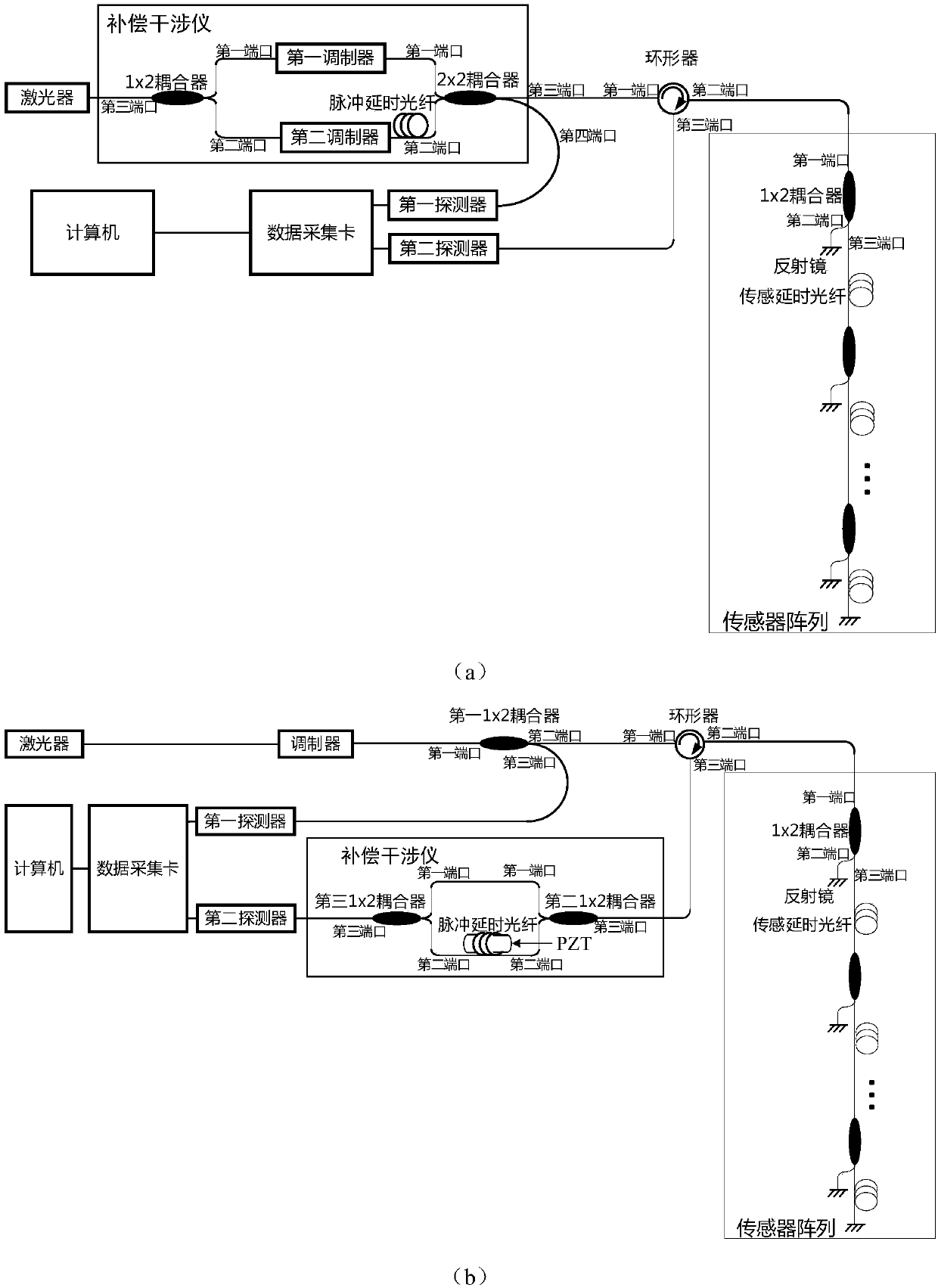
[0062] Such as figure 1 As shown in (a), the suppression system of the multiplicative noise of the time-division multiplexing optical fiber sensing system adopting the heterodyne method of the present embodiment comprises: the suppression system of the multiplicative noise of the time-division multiplexing optical fiber sensing system comprises: a laser, a compensating interferometer , a sensor array, a first detector, a second detector, a data acquisition card and a computer. The compensation interferometer includes a first modulator, a second modulator, a 1×2 coupler, a 2×2 coupler and a pulse delay fiber.

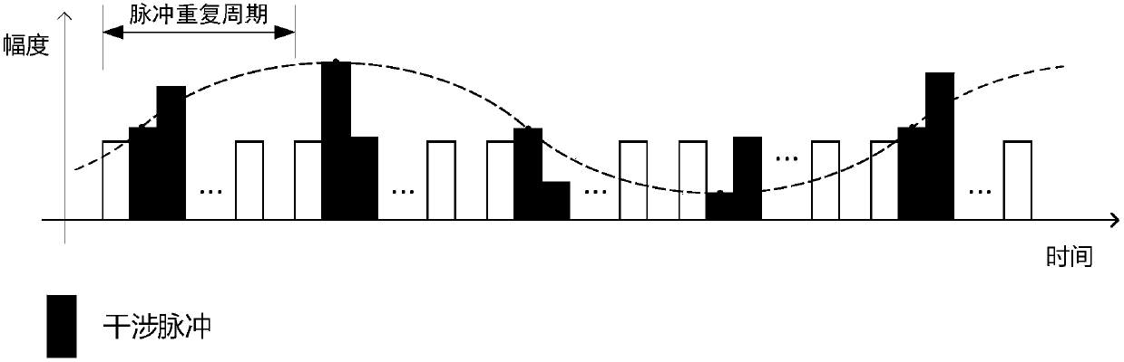
[0063] Such as figure 2 As shown, in each pulse period, N interference pulses will be obtained on the second detector.

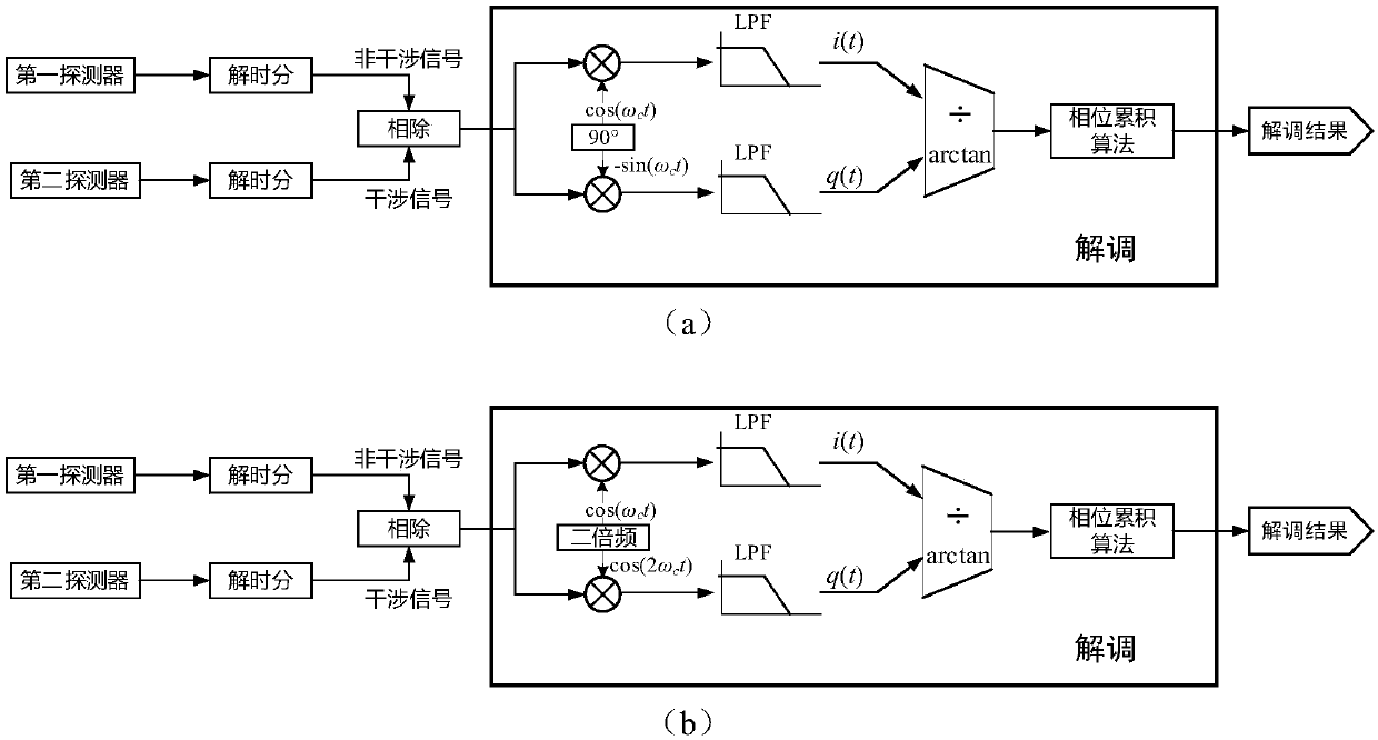
[0064] The computer obtains the non-interference signal and the interference signal after time-dividing the signals obtained from the first detector and the second detector respectively, d...

Embodiment 2

[0071] In this embodiment, the phase generation carrier method is adopted.

[0072] Such as figure 1 As shown in (b), the suppression system of the multiplicative noise of the time-division multiplexing optical fiber sensing system using the phase generation carrier method of the present embodiment includes: the suppression system of the multiplicative noise of the time-division multiplexing optical fiber sensing system includes: a laser, a modulator , a circulator, a sensor array, a first 1×2 coupler, a compensation interferometer, a first detector, a second detector, a data acquisition card and a computer. The compensating interferometer includes the second and third 1×2 couplers, piezoelectric ceramic PZT and pulse delay fiber.

[0073] Such as image 3 Shown in (b), phase generation carrier method demodulation signal, comprises the following steps:

[0074] a) Combine the signal with the carrier cos(ω c t) and its double frequency cos(2ω c t) items are multiplied;

...


PUM


Abstract

The invention discloses a method for restraining the multiplicative noise of a time division multiplexing optical fiber sensing system. Two detectors receive a non-interference pulse and an interference pulse, by means of the non-interference pulse of the time division multiplexing optical fiber sensing system, and through the adoption of a division method, the multiplicative noise in the sensor interference pulse is restrained, and on the premise that the conditions that the impulse amplitude of the non-interference pulse of the system is sufficient and the additive noise is lower than the multiplicative noise are guaranteed, and a good noise suppression effect can be obtained; in addition, the method is also applicable to a phase generation carrier method and a heterodyne method.

Description

technical field [0001] The invention relates to optical fiber sensing technology, in particular to a method and system for suppressing multiplicative noise in a time-division multiplexing optical fiber sensing system. Background technique [0002] Optical fiber sensor is a new type of sensor, which has the advantages of high sensitivity and anti-electromagnetic interference [1]. However, lasers, modulators and other devices in optical fiber sensing systems are often expensive, so in order to reduce system costs, multiple sensors can be placed in the system in a multiplexing manner, such as wavelength division multiplexing, time division multiplexing and space division multiplexing etc. [2]. A widely used multiplexing method is time-division multiplexing, which has various implementation schemes, such as ladder structure, Inline-Michelson structure and low-precision F-P structure [3]. Among them, the ladder structure needs to use a large number of couplers, so the system is...

Claims


Application Information

Patent Timeline
Patent Type & Authority Applications(China)
IPC IPC(8): G01D5/353
CPCG01D5/35306
Inventor 刘飞张敏何向阁古利娟易多
Owner PEKING UNIV
Why Eureka
Try Eureka