
Meteorological radar equipment adopting organic electroluminescence device

A technology of electroluminescent devices and weather radar, which is applied in the direction of radio wave reflection/re-radiation, instruments, and utilization of re-radiation, etc., which can solve the problems of low life and low efficiency

Inactive Publication Date: 2018-09-28
陈永兵
View PDF7 Cites 0 Cited by
  • Summary
  • Abstract
  • Description
  • Claims
  • Application Information

AI Technical Summary

Problems solved by technology

However, the display device of the existing weather radar is still a traditional LED device, which has low life and low efficiency in complex environments

Method used


Image

  • Meteorological radar equipment adopting organic electroluminescence device

Examples


Embodiment Construction

[0013] The technical solutions in the embodiments of the present invention will be described clearly and in detail below with reference to the drawings in the embodiments of the present invention. The described embodiments are only some of the embodiments of the invention.

[0014] The technical scheme that the present invention solves the problems of the technologies described above is:

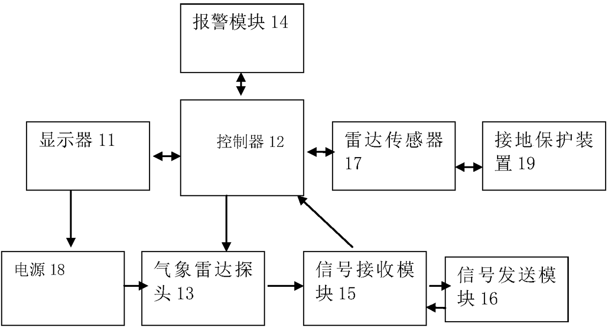
[0015] Such as figure 1Shown is a weather radar device using an organic electroluminescent device, which includes a display 11, a controller 12, a weather radar probe 13, an alarm module 14, a signal receiving module 15, a signal sending module 16, a radar sensor 17, and a power supply module 18 and ground protection device 19, wherein, the display 11 that adopts organic electroluminescence device is connected with power supply module 18 and controller 12 respectively, and described meteorological radar probe 13 is connected with signal receiving module 15, signal sending module 16 and The...


PUM


Abstract

The invention discloses meteorological radar equipment adopting an organic electroluminescence device. The equipment is characterized by comprising a displayer, a controller, a meteorological radar probe, an alerting module, a signal receiving module, a signal sending module, a radar sensor, a power source module and a grounding protection device, wherein the displayer is connected to the power source module and the controller separately, the meteorological radar probe is connected to the signal receiving module, the signal sending module and the controller separately, the alerting module is connected to the controller, the radar sensor is connected to the controller, and the grounding protection device is connected to the radar sensor. The service life of meteorological radar displayer equipment can be prolonged, and the detection accuracy of a meteorological radar is improved.

Description

technical field [0001] The invention belongs to the technical field of radar equipment, in particular to weather radar equipment using organic electroluminescent devices. Background technique [0002] Along with the organic electroluminescence device with microcavity structure of prior art, comprise light-emitting layer, wherein, light-emitting layer comprises a plurality of light-emitting regions arranged in array, light-emitting region is organic electroluminescent region, and the color of light-emitting region can comprise Red, green and blue, represented by R, G, B respectively; the hole transport layer, anode and reflective layer arranged in sequence on one side of the self-luminous layer; the electron transport layer, cathode arranged in sequence on the other side of the self-luminous layer and a semi-transparent and semi-reflective layer; in the hole transport layer, a hole transport area with a preset thickness is provided at a position opposite to the light emitting...

Claims


Application Information

Patent Timeline
Patent Type & Authority Applications(China)
IPC IPC(8): G01S13/95G01S7/06
CPCG01S7/062G01S13/95Y02A90/10
Inventor 李勇臣
Owner 陈永兵
Learn More