
Laser ranging auxiliary optical image combined adjustment method and system

A technology of optical imaging and laser ranging, applied in the field of surveying and mapping, can solve the problems of unfavorable emergency processing, the inability to accurately predict the ground control situation in the target area, and the processing timeliness cannot meet quasi-real-time and other problems

Active Publication Date: 2018-09-28
WUHAN UNIV
View PDF13 Cites 5 Cited by
  • Summary
  • Abstract
  • Description
  • Claims
  • Application Information

AI Technical Summary

Problems solved by technology

At present, these platforms often use laser ranging for target positioning, which requires the laser to lock the target during target ranging, which is not conducive to emergency treatment in the case of multiple targets
In the field of traditional photogrammetry, the image taken by the optical camera is used for block adjustment to obtain the accurate internal and external orientation elements of the image, and then the front intersection method is used to obtain the ground position of the target. The advantage is that the accuracy of target positioning is better than that of laser positioning. method, the disadvantage is that the technical process is complex, and the processing time cannot meet the quasi-real-time requirements
In addition, due to the temporary nature of the mission of the reconnaissance platform, it is impossible to accurately predict the ground control situation in the target area in advance, so only the uncontrolled adjustment technology in the field of photogrammetry can be used, and the accuracy of this technology often depends on the accuracy of the platform observation equipment itself
Moreover, in the process of beam adjustment, a large number of object space points as unknowns increases the processing burden on the platform machine, which is not conducive to the popularization and application of this technology

Method used


Image

  • Laser ranging auxiliary optical image combined adjustment method and system
  • Laser ranging auxiliary optical image combined adjustment method and system
  • Laser ranging auxiliary optical image combined adjustment method and system

Examples


Embodiment Construction

[0051] The invention provides a method for joint adjustment of optical images assisted by laser ranging, which is suitable for scouting and measuring platforms that provide optical images and laser ranging devices, wherein the optical images are used for target observation and tracking, and the laser ranging devices are used for measuring The distance from the platform to the target area is mainly used in the acquisition of the outer orientation elements of the image without direct ground control information and high-precision target positioning. Practical applications have shown that some reconnaissance platforms are equipped with such measurement devices, and in reconnaissance missions, the target area is usually far away from the observation platform, optical images are taken at a large angle, and the observation range of the target area is limited. It is also impossible to provide ground control points at any time during the mission, so the laser ranging value has become th...


PUM


Abstract

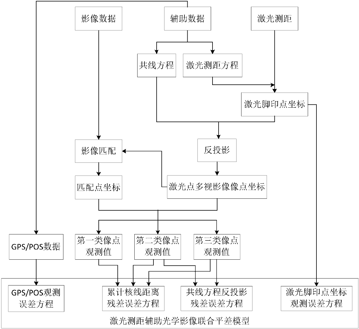
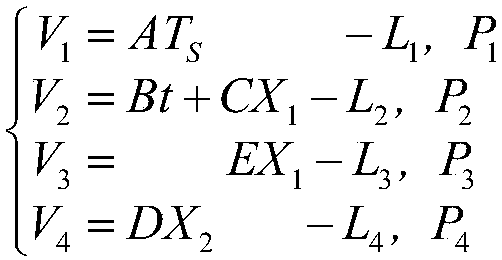
The invention provides a laser ranging auxiliary optical image combined adjustment method and system. According to the method and the system, homonymy matching points of all images serve as a first type of image point observation values, a back projection point of a laser footprint point on a certain image and matching points of the back projection point on other images serve as a second type of image point observation values, the obtained back projection points of the laser footprint point on all images serves a third type of image point observation values, mean square roots of the distance from cumulative points to a nuclear line serve as direct observation values, and a corresponding error equation is listed; the laser footprint points are regarded as low-precision control points, and acorresponding coordinate observation equation is listed; a GPS or POS error observation equation is combined to form a laser ranging auxiliary optical image combined adjustment model, and precise outer orientation elements of the images are solved by using a least squares adjustment criterion. The requirements of high-precision earth observation positioning under a condition of no direct ground control can be fully met.

Description

technical field [0001] The invention belongs to the field of surveying and mapping science and technology, and relates to a combined optical image adjustment technology aided by laser ranging. Background technique [0002] With the development of sensor technology, integrating multiple sensors on some UAV platforms to give full play to the data acquisition capabilities of each sensor has increasingly become a research hotspot in the field of traditional surveying, mapping and remote sensing, and how to carry out joint processing of multi-sensor data is one of them. one of the key technologies. On the current reconnaissance platforms, part of the equipment is integrated with inertial integrated navigation devices, such as GPS / IMU, Beidou system, high-frequency optical cameras and laser measurement devices, which makes these platforms not only have conventional reconnaissance attributes, but also make them an attack weapon. At present, these platforms often use laser ranging...

Claims


Application Information

Patent Timeline
IPC IPC(8): G01S17/42G01S17/02G01S7/497G06F17/11
CPCG01S7/497G01S17/006G01S17/42G06F17/11G01S17/86
Inventor 张永军谢勋伟李彦胜王祥
Owner WUHAN UNIV
Learn More