Power supply patch board

A technology of power strips and conductive rods, which is applied in the direction of circuits, electrical components, coupling devices, etc., can solve the problems of limited number of row jacks, small row jacks, occupation, etc., and achieve the effect of random disassembly and assembly

Inactive Publication Date: 2018-09-28
金庆波
View PDF1 Cites 3 Cited by
  • Summary
  • Abstract
  • Description
  • Claims
  • Application Information

AI Technical Summary

Problems solved by technology

[0002] In the prior art, the power strip generally solves the problem of insufficient power jacks, so there are often multiple jacks arranged side by side on the strip, but due to the limited length of the strip, the number of the jacks is limited, and the power supply The jacks are very small, and nowadays, the electrical plugs we use are getting bigger and bigger. This kind of large plug is inserted behind the jack of the row, and its size is too large, which will cause the plug to occupy two jack positions. Interfering with the use of other plugs on one side, resulting in a waste of the number of sockets

Method used


Image

  • Power supply patch board
  • Power supply patch board
  • Power supply patch board

Examples


Embodiment Construction

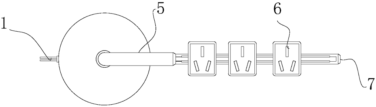
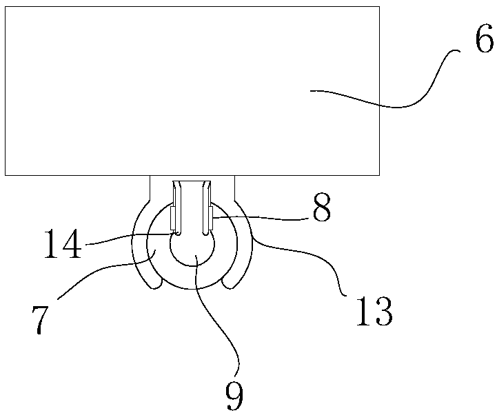
[0015] Such as figure 1 with figure 2 As shown, the power strip includes a base 2, a bearing 3 is embedded in the center of the upper end of the base 2, a connecting shaft 5 is inserted into the bearing hole of the bearing 3, and a bending part (not shown) is arranged at the bottom of the connecting shaft 5 ), the bending part is installed in the bearing hole of the bearing, a conductive rod 7 is fixedly arranged on the outer end of the connecting shaft 5, a conductive cavity 9 is formed in the middle of the conductive rod 7, and a conductive copper row is embedded on both sides of the inner wall of the conductive cavity 9 8. One end of the conductive copper bar 8 protrudes from the outer surface of the conductive chamber 9 , and more than one socket module 6 is detachably installed on the upper end surface of the conductive rod 7 .

[0016] Among them, such as image 3 As shown, the lower end surface of the socket module 6 is provided with an arc-shaped connecting sleeve 1...


PUM


Abstract

The invention discloses a power supply patch board. The power supply patch board comprises a base; a bearing is embedded in the center of the upper end of the base; a connecting shaft is mounted in abearing hole of the bearing; a bent part is arranged at the bottom of the connecting shaft; the bent part is mounted in the bearing hole of the bearing; a conductive rod is fixedly arranged at the outer side end of the connecting shaft; a conductive cavity is formed in the middle of the conductive rod; conductive copper bars are embedded in the two sides of the inner walls of the conductive cavityrespectively; one ends of the conductive copper bars extend out of the outer side surface of the conductive cavity; and one or more socket modules are detachably mounted on the upper end plane of theconductive rod. By virtue of the power supply patch board, random detachment of each socket module can be realized, the number of the socket modules can be changed according to needs, the socket modules can glided freely, the spacing between the socket modules can be adjusted, and mutual influence between plugs in use can be avoided.

Description

technical field [0001] The invention relates to the field of sockets, in particular to a power strip. Background technique [0002] In the prior art, the power strip generally solves the problem of insufficient power jacks, so there are often multiple jacks arranged side by side on the strip, but due to the limited length of the strip, the number of the jacks is limited, and the power supply The jacks are very small, and nowadays, the electrical plugs we use are getting bigger and bigger. This kind of large plug is inserted behind the jack of the row, and its size is too large, which will cause the plug to occupy two jack positions. It interferes with the use of other plugs on one side, resulting in a waste of the number of sockets. Contents of the invention [0003] The technical problem to be solved by the present invention is to provide a power strip, which can realize the random disassembly and assembly of each socket module, and can increase or decrease the quantity ...

Claims


Application Information

Patent Timeline
Patent Type & Authority Applications(China)
IPC IPC(8): H01R13/514H01R25/14
CPCH01R25/145H01R13/514H01R25/142
Inventor 金庆波
Owner 金庆波
Why Eureka
Try Eureka