Check patentability & draft patents in minutes with Patsnap Eureka AI!

Star chain type STATCOM based on auxiliary power unit and control method

A chain and power loop technology, applied in the direction of reactive power adjustment/elimination/compensation, electrical components, AC network circuits, etc., can solve problems such as limited unbalanced reactive power compensation capability, reduced system complexity, unbalanced, etc. To achieve the effect of improving unbalanced reactive power compensation capability and power density

Active Publication Date: 2018-09-28
NANJING UNIV OF SCI & TECH
View PDF6 Cites 5 Cited by
  • Summary
  • Abstract
  • Description
  • Claims
  • Application Information

AI Technical Summary

Problems solved by technology

The traditional chained STATCOM topology can be divided into star structure and delta structure. Under the same voltage level, the star structure can use fewer units, thereby greatly reducing the complexity of the system, but the unbalanced reactive power compensation capability of the structure very weak
[0003] Invention patents CN201510196420.6 and CN201310101371.4 disclose the method of using zero-sequence voltage injection to realize a small amount of energy exchange between phases, but due to the constraints of hardware topology, the software method can only perform a small amount of unbalanced reactive power compensation, unbalanced reactive power limited ability to compensate
Invention patent CN201220674796.5 discloses a star-connected chained STATCOM device with unbalanced current compensation function. It uses a power frequency transformer to provide a zero-sequence current loop to realize energy exchange between phases, thereby achieving any unbalanced compensation. However, the structure The industrial frequency transformer is very bulky and does not use the power density of the device to increase

Method used


Image

  • Star chain type STATCOM based on auxiliary power unit and control method
  • Star chain type STATCOM based on auxiliary power unit and control method
  • Star chain type STATCOM based on auxiliary power unit and control method

Examples


Embodiment Construction

[0019] The solutions of the present invention will be further described below in conjunction with the accompanying drawings and specific embodiments.

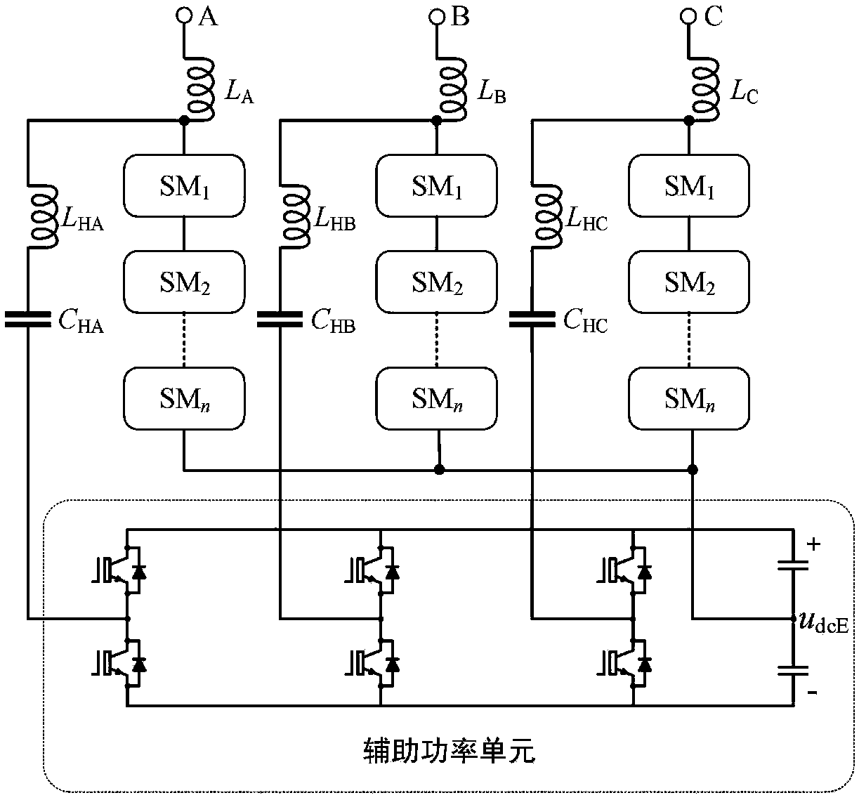
[0020] Star chain STATCOM based on auxiliary power unit and its control method. The system includes an auxiliary power unit and three LC series resonant circuits, the auxiliary power unit includes six power switch tubes, six diodes and two energy storage capacitors, and the six power switch tubes are respectively connected in antiparallel with one diode , forming six switch tube modules, the six switch tube modules are connected in series in pairs to form three switch tube series circuits, the midpoints of the three switch tube series circuits are respectively connected to the three-phase chain link through an LC series resonant circuit At the inductance end, the two energy storage capacitors are connected in series to form a capacitor series circuit, the capacitor series circuit is connected in parallel with the switch tube se...


PUM


Abstract

The invention discloses a star chain type STATCOM based on an auxiliary power unit and a control method of the star chain type STATCOM. The system comprises an auxiliary power unit and three LC seriesresonance circuits, wherein the auxiliary power unit comprises six power switch tubes, six diodes and two energy storage capacitors; the six power switch tubes are reversely connected to one diode inparallel to form six switch tube modules; every two of the six switch tube modules are connected in series to form three switch tube series circuits; middle points of the three switch tube series circuits are connected to an inductance end of a three-phase link respectively through one LC series resonance circuit; the two energy storage capacitors are connected in series to form a capacitor series circuit; the capacitor series circuit and the switch tube series circuit are connected in parallel; and the middle point of the capacitor series circuit is connected to the middle point of a three-phase star link. According to the star chain type STATCOM based on the auxiliary power unit and the control method, the unbalanced reactive compensation capability of the star chain type STATCOM and the power density of the device are improved.

Description

Technical field: [0001] The invention relates to high-voltage and high-power power electronic technology, in particular to a star chain STATCOM based on an auxiliary power unit and a control method thereof. Background technique: [0002] Chained STATCOM has been widely used in the field of power quality management of medium and high voltage distribution networks. It has the characteristics of modularization and easy expansion, and can be directly integrated into medium and high voltage power grids without transformers. The traditional chained STATCOM topology can be divided into star structure and delta structure. Under the same voltage level, the star structure can use fewer units, thereby greatly reducing the complexity of the system, but the unbalanced reactive power compensation capability of this structure very weak. [0003] Invention patents CN201510196420.6 and CN201310101371.4 disclose the method of using zero-sequence voltage injection to realize a small amount of...

Claims


Application Information

Patent Timeline
Patent Type & Authority Applications(China)
IPC IPC(8): H02J3/18
CPCH02J3/1821Y02E40/10
Inventor 季振东王乾同程路吕建国赵志宏姚佳赵剑锋
Owner NANJING UNIV OF SCI & TECH
Features
  • R&D
  • Intellectual Property
  • Life Sciences
  • Materials
  • Tech Scout
  • Unparalleled Data Quality
  • Higher Quality Content
  • 60% Fewer Hallucinations
Learn More