Electromagnetic heating die

A mold, electromagnetic technology, applied in the direction of ohmic resistance heating, electric heating device, induction heating, etc., can solve the problems of infeasibility, inability to directly heat materials, unsatisfactory effect, etc., to achieve the effect of shortening the heating time

Pending Publication Date: 2018-09-28
丰泽智能装备股份有限公司 +3
View PDF0 Cites 5 Cited by
  • Summary
  • Abstract
  • Description
  • Claims
  • Application Information

AI Technical Summary

Problems solved by technology

After actual tests, the inventor found that the effect of this heating method is not ideal, because the mold itself is made of metal materials, which have a strong shielding effect on electromagnetic fields, and the alternating magnetic field gene

Method used


Image

  • Electromagnetic heating die
  • Electromagnetic heating die

Examples


Example Embodiment

[0026] Example 1

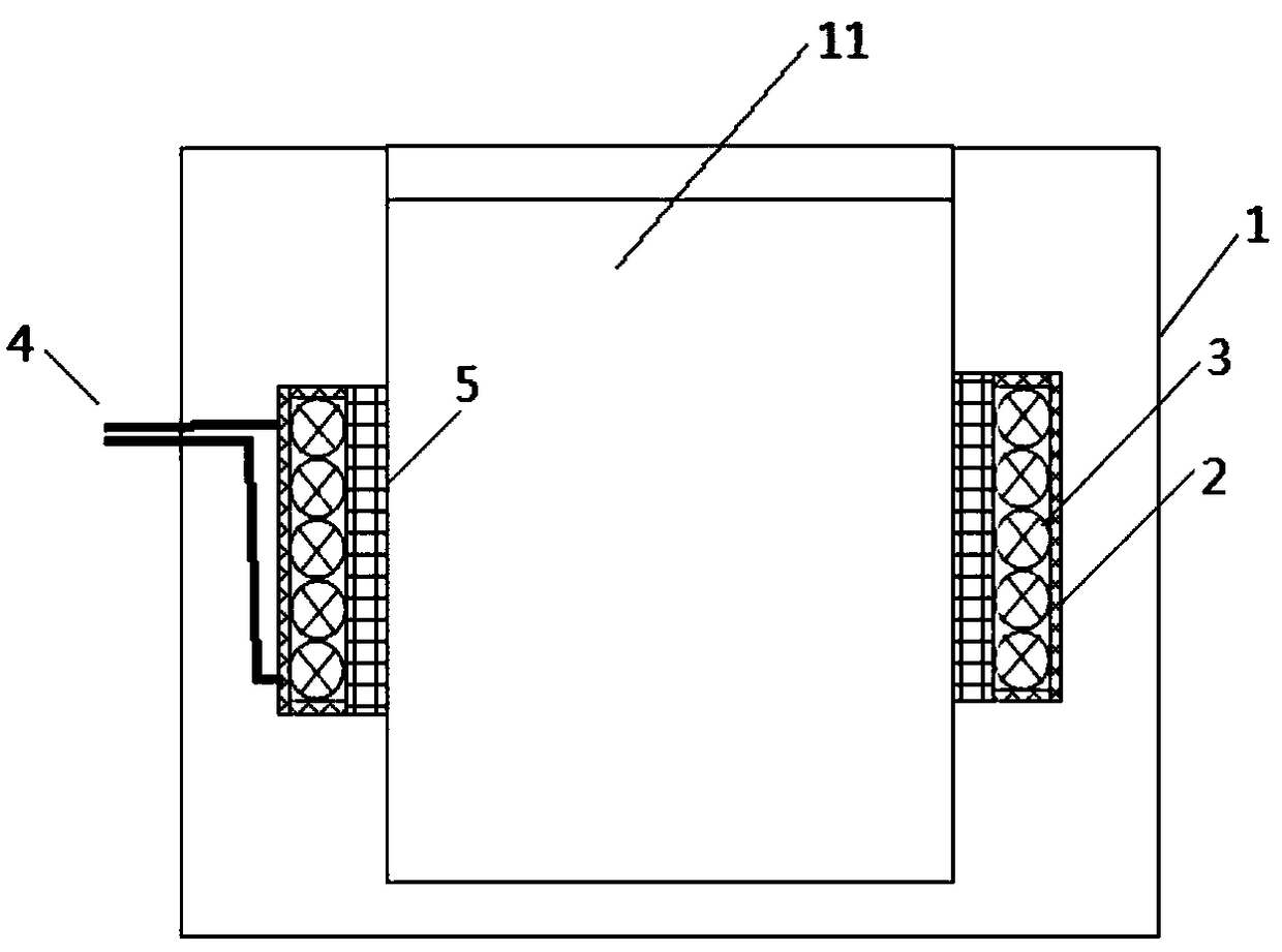
[0027] This embodiment provides an electromagnetic heating mold, such as figure 1 As shown, it includes a mold body 1 with a hollow cavity 11 suitable for placing the parts to be heated. The material of the mold body 1 can be selected from metallic materials or non-metallic materials. A containing groove is opened at a set position on the inner wall of the hollow cavity 11, and the opening of the containing groove faces the inside of the hollow cavity 11 and is arranged around the inner wall of the cavity 11. A magnetically conductive groove 2 is fixedly arranged in the receiving groove. The magnetically conductive groove 2 is made of a magnetically conductive ceramic material, and its opening faces the hollow cavity 11, and the magnetically conductive ceramic material has good insulation. It can confine the electromagnetic field within a certain range. Inside the magnetic conducting slot 2, a wire 4 is arranged. The conducting wire 4 is coiled inside the magn...

Example Embodiment

[0035] Example 2

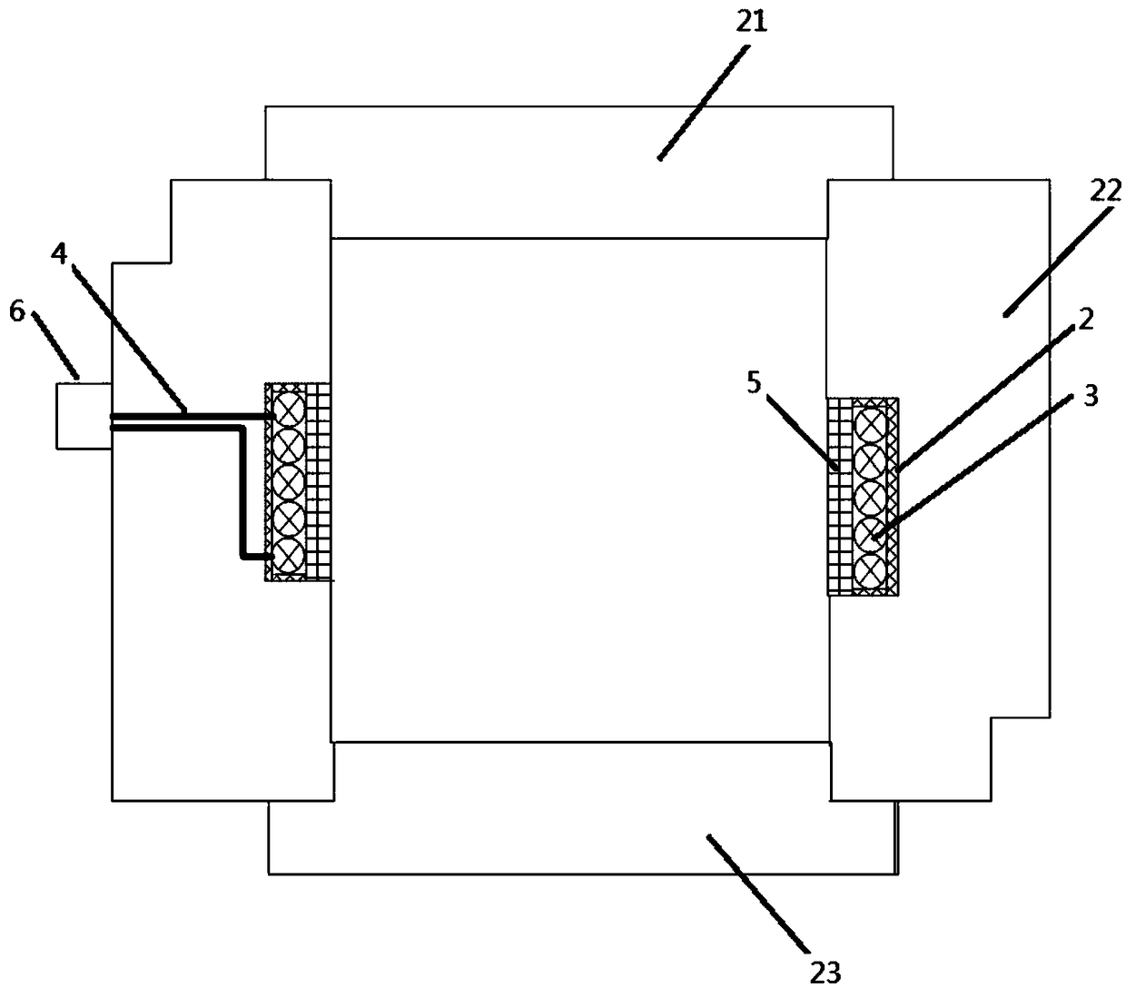
[0036] The electromagnetic heating mold provided in this embodiment, such as figure 2 As shown, the side wall of the mold body is provided with a connector 6; the two ends of the wire 4 pass through the magnetic groove 2 and the mold body and are electrically connected to the first end of the connector 6 The middle and high frequency power supply is electrically connected to the second end of the connector 6. The connector 6 can be realized by selecting an industrial waterproof connector, which can be products produced by manufacturers such as Chint Electric, Delixi Electric, etc.

[0037] Wire passage holes are opened on the bottom of the magnetic conductive groove 2 and the side wall of the hollow cavity 11; the wire inlet and outlet ends of the wire 4 pass through the wire hole and connect with the connector 6 The first end is connected; a sealant is poured between the wire 4 and the wire-through hole, so as to achieve the overall sealing of the mold.

[003...


PUM


Abstract

The invention provides an electromagnetic heating die. A magnetic conducting groove prepared from a magnetic conducting ceramic material and used for accommodating an electrified coil is formed in thedie body of the electromagnetic heating die; the electrified coil can be electrically connected with a middle-high-frequency power supply on the exterior of the die body so as to obtain a middle-high-frequency current to generate an alternating magnetic field; the electrified coil is directly arranged in the die body and placed in the magnetic conducting groove, so that the generated alternatingmagnetic field is constrained in the die body, so that a condition that the alternating magnetic field only acts on the die body is avoided. By virtue of the scheme, the middle-high-frequency alternating magnetic field is all applied to direct heating on a to-be-heated part, so that a very high heating effect is achieved, thereby highly shortening the heating time.

Description

Technical field [0001] The invention belongs to the technical field of electromagnetic applications, and specifically relates to an electromagnetic heating mold that directly heats internal parts of the mold by using an electromagnetic field. Background technique [0002] Different industries often encounter the need for heating materials, and various heating methods are also designed according to different demand scenarios. The most common heating method is to achieve heat conduction through an intermediate medium (such as heat transfer oil), that is, first heat the intermediate medium to reach a high temperature, and then contact the material to be heated with the intermediate medium, and heat the material to the required level through heat conduction Temperature, but the above heating method is applied to some special structures or special materials with low efficiency and poor uniformity. For example, when heating some materials with poor thermal conductivity, they are gener...

Claims


Application Information

Patent Timeline
IPC IPC(8): H05B6/10H05B6/36H05B6/40
CPCH05B6/10H05B6/36H05B6/40H05B2206/022
Inventor 徐瑞祥李炯李晓明赵前程刘驰秦倞韩文涛张亚军王晶
Owner 丰泽智能装备股份有限公司
Why Eureka
Try Eureka