Water conserving shower system and thermochromic fixtures used therein

A thermochromic and shower system technology, applied in the field of water-saving shower systems and thermochromic devices used therein, can solve the problems of inconvenience, discomfort, waste, etc.

Active Publication Date: 2018-09-28
AQUA VIEW INC
View PDF8 Cites 4 Cited by
  • Summary
  • Abstract
  • Description
  • Claims
  • Application Information

AI Technical Summary

Problems solved by technology

This "not hot" stream goes directly to the sewer where it is wasted
As a result, fresh water tanks must be filled more often (which is often not feasible), or water consumption in craft or vehicles must be limited to levels that many users would find inconvenient or uncomfortable

Method used


Image

  • Water conserving shower system and thermochromic fixtures used therein
  • Water conserving shower system and thermochromic fixtures used therein
  • Water conserving shower system and thermochromic fixtures used therein

Examples


Embodiment Construction

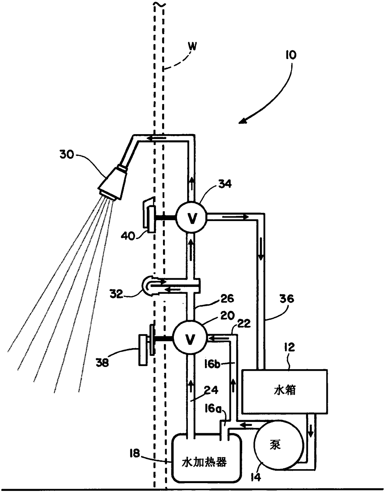
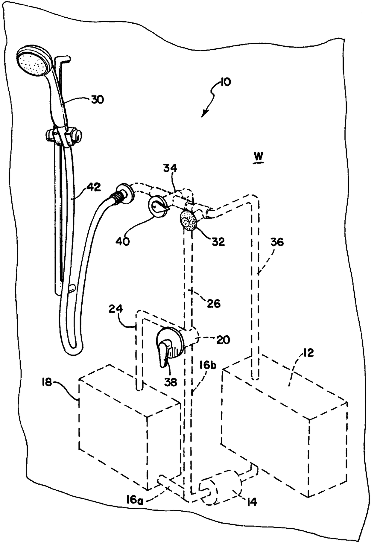
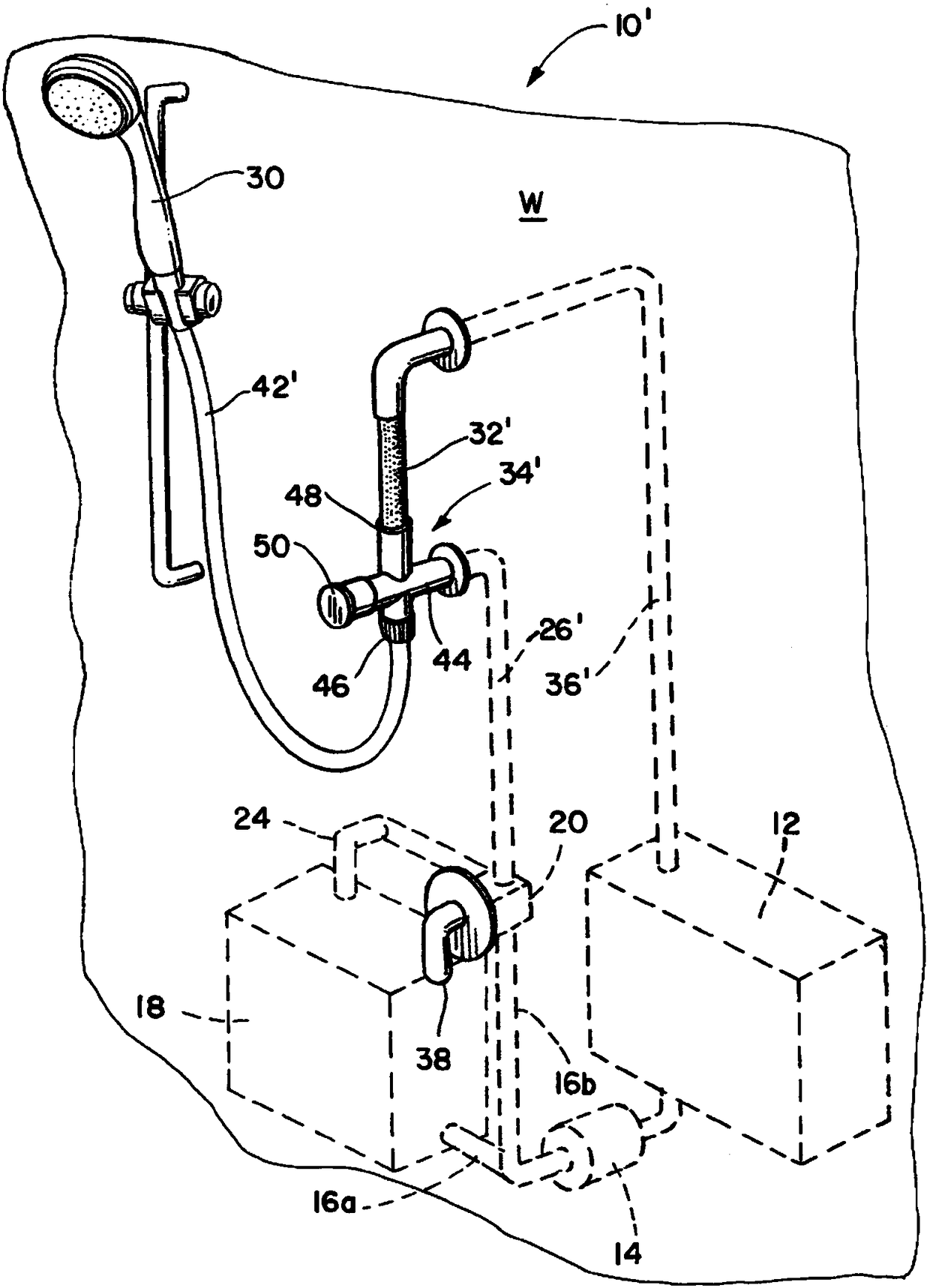
[0023] Referring now to the accompanying drawings, figure 1 A water saving shower system 10 for mobile applications is shown according to one aspect of the present disclosure. The system 10 is suitable for use in a land vehicle such as an RV or trailer, or a watercraft such as a boat or watercraft. System 10 employs a reservoir or tank 12 of fixed volumetric capacity configured to be filled with water, typically fresh water. A pump 14 (usually electric) pumps water from the tank 12 to the tank outlet conduit having a first branch 16a leading the water to a conventional water heating unit 18, and a second branch through a cold water conduit 22 and a mixing valve 20. An inlet 19 is fluidly connected to the second branch 16b. The water in tank 12 is typically at ambient temperature and may be referred to as "cold" water for the purposes of this disclosure. A hot water conduit 24 leads heated water from the heating unit 18 to the second inlet 23 of the mixing valve 20 . The wa...


PUM


Abstract

A water delivery system includes a mixing valve operable for delivering a water flow of adjustable temperature from a water source to a dispensing device downstream from the mixing valve; a thermochromic thermal indicator, fluidly coupled between the mixing valve and the dispensing device, that provides a visible indication of the water flow having achieved a predetermined temperature; and a diverter valve, fluidly coupled between the mixing valve and the dispensing device, and operable to direct the water flow selectively either to the dispensing device or back to the water source. The thermal indicator may be a thermochromic PVC conduit, or may be a fitting having an inlet, an outlet, a thermochromic PVC element therebetween, and a barrier located between the inlet and the outlet so as to define a flow path that includes an interior surface of the thermochromic element.

Description

[0001] Cross References to Related Applications [0002] This application claims priority to US Application No. 14 / 937,587, filed November 10, 2015, the disclosure of which is incorporated herein by reference in its entirety. [0003] Federally Sponsored Research or Development [0004] Not applicable. Background technique [0005] In a first aspect, the present disclosure relates to domestic plumbing systems, particularly shower systems, which employ a thermochromic device to provide a visual indication of water temperature so that the water can be recirculated to a reservoir until a predetermined temperature is reached and the water is allowed to Flows out of the shower head when a predetermined temperature is reached. In a second aspect, the present disclosure also relates to a method of saving water in a domestic plumbing system by using a thermochromic device in such a system. In a third aspect, the present disclosure relates to thermochromic devices for use in the sys...

Claims


Application Information

Patent Timeline
Patent Type & Authority Applications(China)
IPC IPC(8): E03C1/04E03C1/044E03C1/02
CPCE03C1/02E03C1/025E03C1/04E03C1/044B60R15/02B63B29/02B63B2029/022G01K13/02G01K2207/00B05B1/3093E03B7/045B05B1/18E03C1/0408E03C2201/30G01K11/12G01K13/026E03C2001/0418F16K19/00
Inventor 格斯·瑟西
Owner AQUA VIEW INC
Why Eureka
Try Eureka