Eureka AIR delivers breakthrough ideas for toughest innovation challenges, trusted by R&D personnel around the world.

A wavelength drift control method and system

A wavelength drift and control system technology, applied in the field of optical communication, can solve the problem that the influence of wavelength drift cannot be well eliminated, and achieve the effect of stabilizing the emission wavelength, avoiding wavelength drift, and realizing stable control.

Active Publication Date: 2020-04-21
HUAWEI TECH CO LTD
View PDF8 Cites 0 Cited by
  • Summary
  • Abstract
  • Description
  • Claims
  • Application Information

AI Technical Summary

Problems solved by technology

[0004] However, if the driving current is reduced, the emission function of the laser will be affected, and the PON system has higher requirements on the emission power of the laser, so reducing the driving current will affect the normal operation of the PON system. It can be seen that this method cannot It is very good to eliminate the impact of wavelength drift on the normal operation of the multi-wavelength channel PON system

Method used


Image

  • A wavelength drift control method and system
  • A wavelength drift control method and system
  • A wavelength drift control method and system

Examples


Embodiment Construction

[0051] The following will clearly and completely describe the technical solutions in the embodiments of the present invention with reference to the accompanying drawings in the embodiments of the present invention. Obviously, the described embodiments are only some, not all, embodiments of the present invention. Based on the embodiments of the present invention, all other embodiments obtained by those skilled in the art without creative efforts fall within the protection scope of the present invention.

[0052] The terms "first", "second", "third", "fourth", etc. (if any) in the description and claims of the present invention and the above drawings are used to distinguish similar objects, and not necessarily Used to describe a specific sequence or sequence. It is to be understood that the terms so used are interchangeable under appropriate circumstances such that the embodiments described herein can be practiced in sequences other than those illustrated or described herein. F...


PUM


Abstract

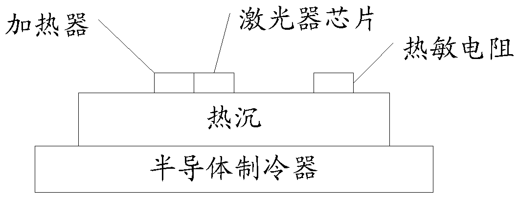
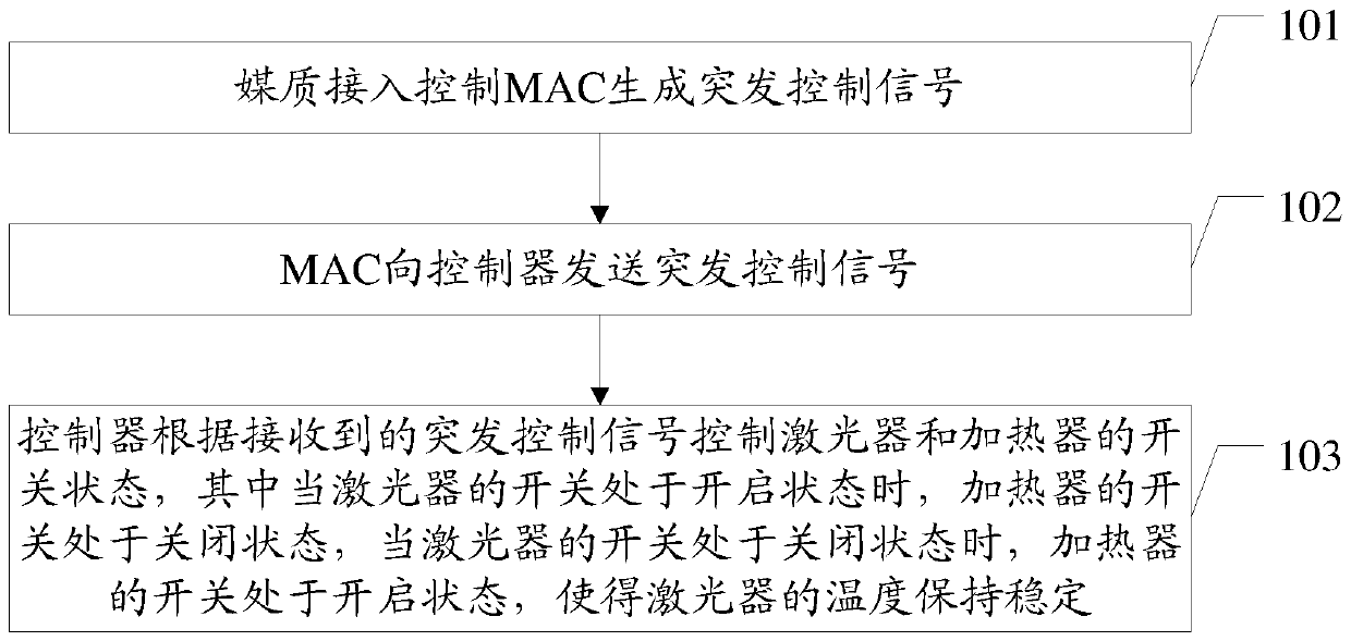
The embodiment of the present invention discloses a wavelength drift control method and system, which realizes the stable control of the temperature of the laser, ensures that the laser emits a stable wavelength during the burst operation of the transmitter, does not drift, and avoids multi-wavelength channels. The normal operation of the PON system will be affected. The method in the embodiment of the present invention includes: the MAC generates a burst control signal; the MAC sends the burst control signal to the controller; the controller controls the switch state of the laser and the heater according to the received burst control signal , wherein when the switch of the laser is on, the switch of the heater is off, and when the switch of the laser is off, the switch of the heater is on, so that the temperature of the laser keep it steady.

Description

technical field [0001] The invention relates to the field of optical communication, in particular to a wavelength drift control method and system. Background technique [0002] The broadband access technology has developed rapidly in recent years, and the passive optical network (English full name: Passive Optical Network, English abbreviation: PON) system has completed large-scale popularization and rapid expansion. Due to the low-cost requirements of the access network, low-cost access technology will be the main development direction. The low-cost access technology mainly uses wavelength division multiplexing to realize high-capacity PON systems, such as a typical The uplink and downlink of the PON system are composed of four wavelength channels. The interval between each wavelength channel is 100GHz. , the PON system is a point-to-multipoint system, and each optical line terminal (English full name: Optical Line Terminal, English abbreviation: OLT) in the PON system nee...

Claims


Application Information

Patent Timeline
Patent Type & Authority Patents(China)
IPC IPC(8): H04B10/572
CPCH04B10/572H04B10/506H04J14/0246H01S5/0612H01S5/06216H01S5/06804H01S5/02453H04J14/02H01S3/10015H04Q11/0067H04Q2011/0064
Inventor 吴徐明林华枫方李明
Owner HUAWEI TECH CO LTD
Why Eureka
Eureka Blog
Learn More