Tailings recycling equipment

A technology for recycling equipment and tailings, applied in the field of tailings recycling equipment, can solve problems such as loud noise, environmental pollution, damage, etc., and achieve the effect of increasing the number and reducing the spacing.

Inactive Publication Date: 2018-10-02
江西柏立松科技环保设备制造有限公司
View PDF0 Cites 0 Cited by
  • Summary
  • Abstract
  • Description
  • Claims
  • Application Information

AI Technical Summary

Problems solved by technology

[0002] The tailings recovery device can effectively reduce the loss of tailings, control it below 3%, effectively reduce the content of active ingredients in tailings, solve the pollution of tailings to the environment, and meet the emission standards required by environmental protection. It is widely used in metallurgy , mines, water conservancy, hydropower, sand and gravel factories, glass factories, coal preparation plants, crude coal recovery and environmental protection projects, shield machines and other engineering projects; the existing tailings recovery devices have certain disadvantages in use. First, After the existing tailings recovery device is used for a period of time, the magnetic force of the internal disk will weaken, and there will be an area of ​​zero magnetic force at this time, which will affect the recovery effect of the tailings recovery device on ore. Secondly, when recovering the tail water , there will be more residues that cannot be removed and will be directly removed, causing certain pollution to the environment. Finally, the noise generated by the tailings recovery device during work is too large, which has brought certain damage to the surrounding environment and people. People's use process has brought a certain impact, for this reason, we propose a tailings recovery equipment

Method used


Image

  • Tailings recycling equipment
  • Tailings recycling equipment
  • Tailings recycling equipment

Examples


Embodiment Construction

[0017] In order to make the technical means, creative features, goals and effects achieved by the present invention easy to understand, the present invention will be further described below in conjunction with specific embodiments.

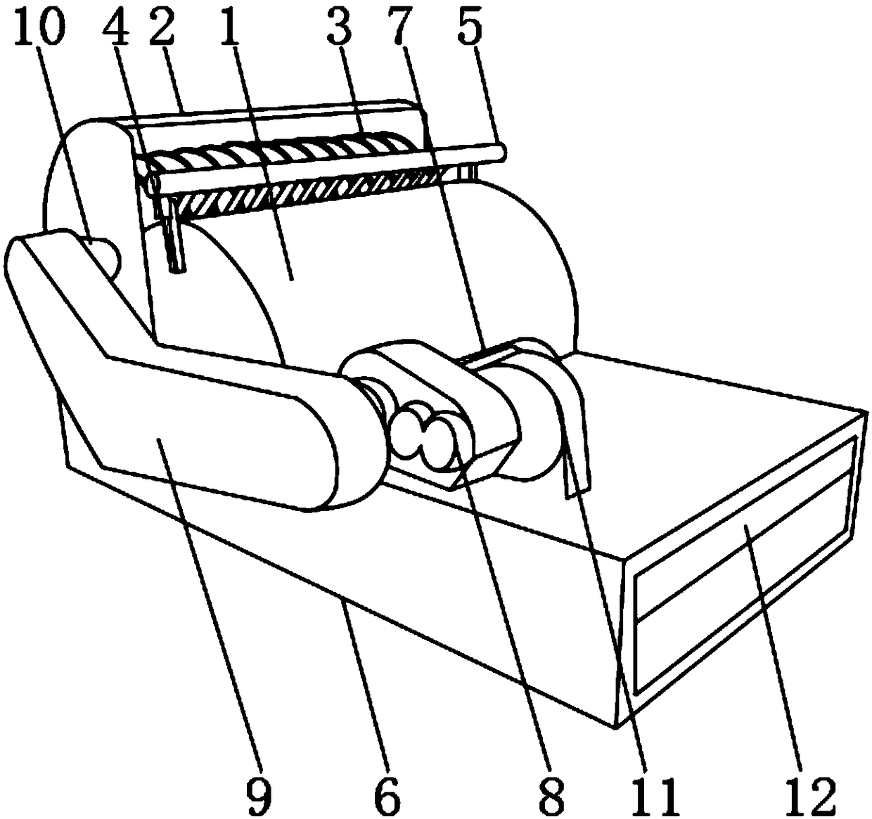
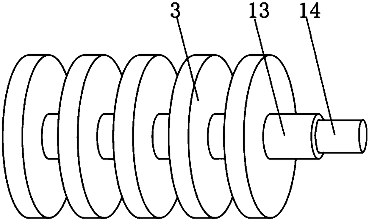
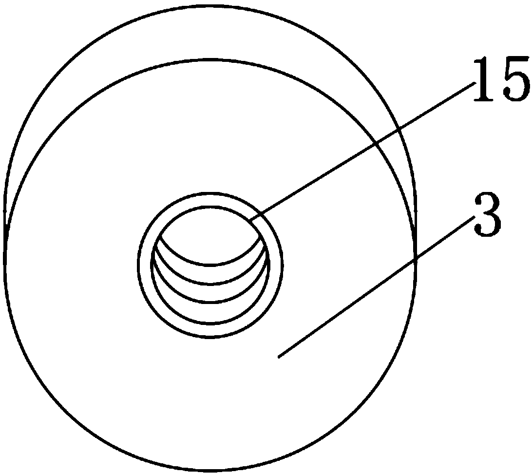
[0018] Such as Figure 1-4 As shown, a tailings recovery equipment includes a chassis 1, a protective cover 2 is fixedly installed above the chassis 1, and a magnetic disk 3 is arranged inside the chassis 1, and connecting rods 4 are fixedly installed on both sides of the chassis 1 near the upper end. And the upper end of connecting rod 4 is fixedly installed with cross bar 5, and the lower end of cabinet 1 is fixedly installed with collection box 6, and the upper end outer surface of collection box 6 is fixedly installed with motor 7 near the front position of cabinet 1, and one part of motor 7 A power box 8 is fixedly installed on the side, and a frame 9 is fixedly installed on one side of the power box 8, and a transmission shaft 10 is arranged...


PUM


Abstract

The invention discloses tailings recycling equipment. The tailings recycling equipment comprises a machine case. A protection cover is fixedly arranged above the machine case. Magnetic discs are arranged in the machine case, and the positions, close to the upper end, of the two sides of the machine case are fixedly provided with connecting rods. A transverse rod is fixedly arranged at the upper ends of the connecting rods. A tailings collecting box is fixedly arranged at the lower end of the machine case, and the position, close to the front portion of the machine case, of the outer surface ofthe upper end of the tailings collecting box is fixedly provided with a motor. A power box is fixedly arranged on one side of the motor, a rack is fixedly arranged on one side of the power box, and the position, close to one end, of the outer surface of one side of the rack is provided with a transmission shaft. The tailings recycling equipment is provided with noise isolation plates, fixing rings and filter nets, noise generated by the tailings recycling equipment can be lowered, and when the magnetic force of the magnetic discs is weakened, the positions of the magnetic discs can be adjusted, residues in tail water are prevented from polluting the environment, and better usage prospects are brought.

Description

technical field [0001] The invention relates to the field of tailings recovery equipment, in particular to a tailings recovery equipment. Background technique [0002] The tailings recovery device can effectively reduce the loss of tailings, control it below 3%, effectively reduce the content of active ingredients in tailings, solve the pollution of tailings to the environment, and meet the emission standards required by environmental protection. It is widely used in metallurgy , mines, water conservancy, hydropower, sand and gravel factories, glass factories, coal preparation plants, crude coal recovery and environmental protection projects, shield machines and other engineering projects; the existing tailings recovery devices have certain disadvantages in use. First, After the existing tailings recovery device is used for a period of time, the magnetic force of the internal disk will weaken, and there will be an area of ​​zero magnetic force at this time, which will affect...

Claims


Application Information

Patent Timeline
Patent Type & Authority Applications(China)
IPC IPC(8): B09B3/00B03C1/02G10K11/16
CPCB09B3/00B03C1/02G10K11/16
Inventor 黄俊
Owner 江西柏立松科技环保设备制造有限公司
Why Eureka
Try Eureka