Gear extrusion forming device

A technology of extrusion molding and gears, which is applied in the direction of wheels, transportation and packaging, vehicle parts, etc., can solve problems such as deformation and unfavorable gear sales, and achieve the effects of reducing time, avoiding deformation and wear, and improving production efficiency

Pending Publication Date: 2018-10-02
重庆亨睿达机械有限公司
View PDF1 Cites 9 Cited by
  • Summary
  • Abstract
  • Description
  • Claims
  • Application Information

AI Technical Summary

Problems solved by technology

Wear, warping, and scratches c

Method used


Image

  • Gear extrusion forming device
  • Gear extrusion forming device
  • Gear extrusion forming device

Examples


Embodiment 2

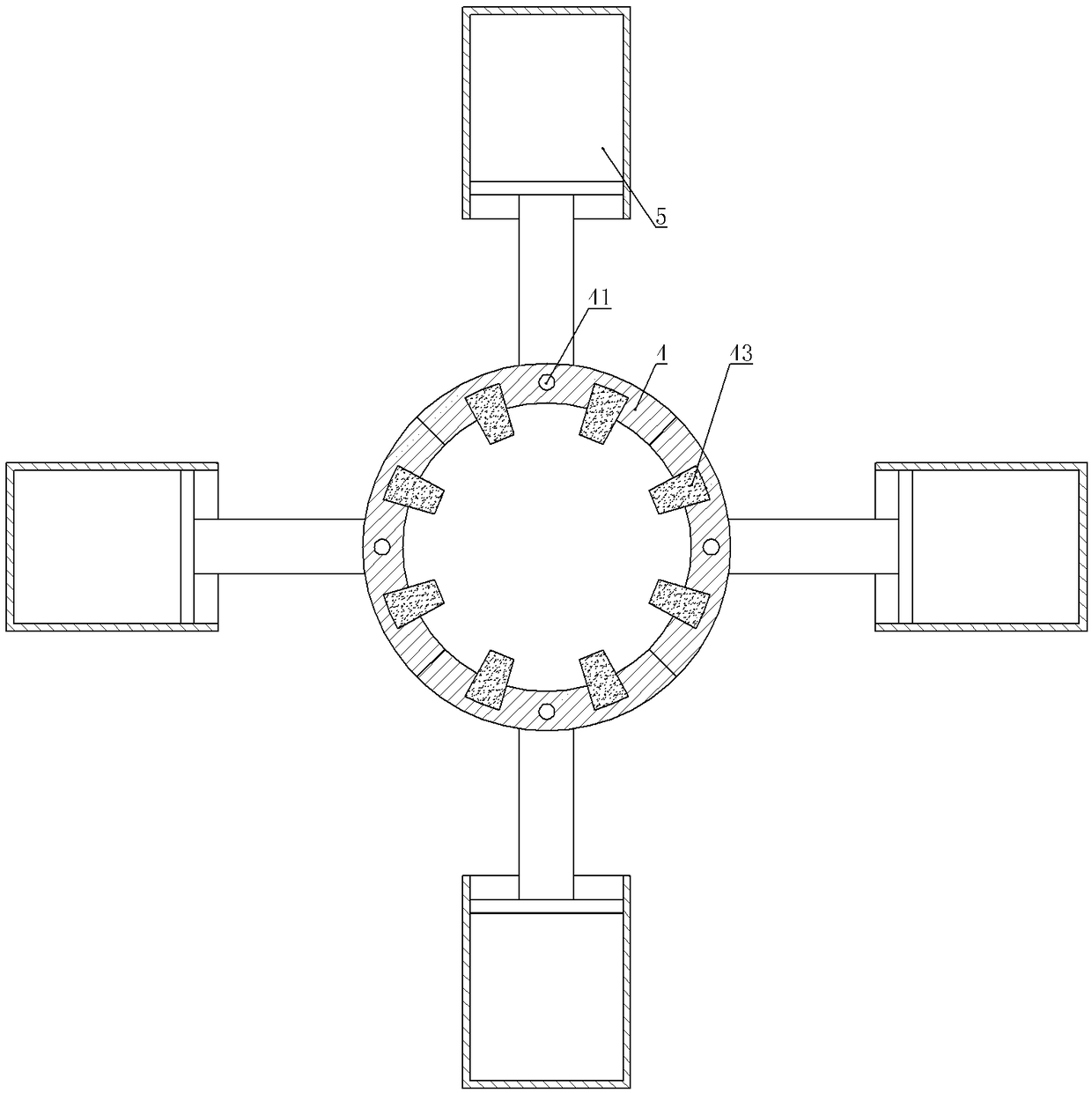
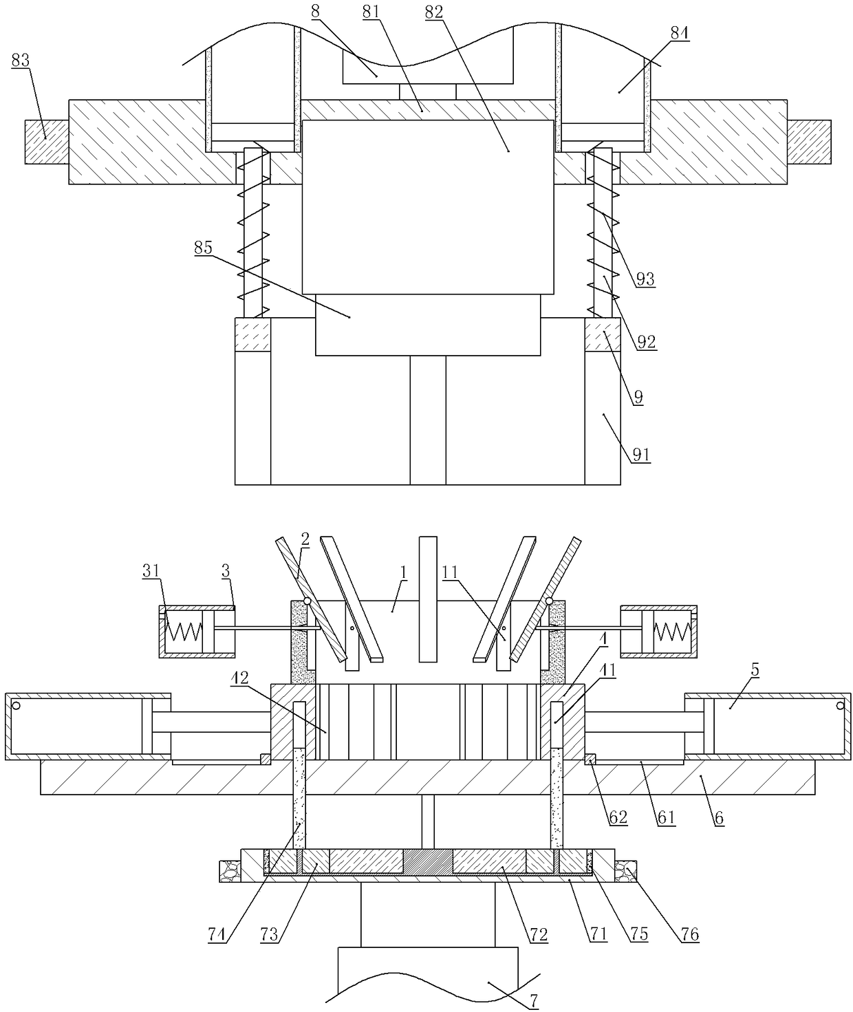
[0037] The difference from Example 1 is that, as image 3 As shown, a support mechanism is also provided between the arc block 4 and the limit ring 9, and the support mechanism includes a feed cylinder 1 welded on the frame 6, eight support cylinders 3 and a hinged joint with the top of the feed cylinder 1. There are eight support pieces 2 , and the inner wall of the feeding cylinder 1 is provided with accommodating grooves 11 that can accommodate the support pieces 2 . The piston rod of the support cylinder 3 runs through the feeding cylinder 1 and is offset against the lower part of the support plate 2. When the limit ring 9 slides downward, the piston rod of the support cylinder 3 is snapped into the passage groove 91, and the support cylinder 3 is provided with two ends The return spring 31 welded on the inner wall of the support cylinder 3 and the piston of the support cylinder 3 respectively, and the end of the support cylinder 3 away from the support plate 2 is provided...


PUM


Abstract

The invention relates to the field of gear machining and particularly discloses a gear extrusion forming device. The gear extrusion forming device comprises a rack, an upper mould mechanism and a lower mould mechanism; the upper mould mechanism comprises a lower sliding hydraulic cylinder, an upper mould base, a squeezing hydraulic cylinder, inflation air cylinders and limiting rings; a punch is fixed to a pushing rod of the squeezing hydraulic cylinder; the limiting rings and the punch are coaxial; the limiting rings can push pistons of the inflation air cylinders to slide; the lower mould mechanism comprises a lower mould, fixing air cylinders and tooth moulds; the lower mould comprises a plurality of arc-shaped blocks; the fixing air cylinders communicate with the inflation air cylinders; piston rods of the fixing air cylinders are fixed to the arc-shaped blocks; tooth mould grooves are formed in one sides, far away from the fixing air cylinders, of the arc-shaped blocks; the toothmoulds are detachably connected with the tooth mould grooves; and through grooves allowing the piston rods of the fixing air cylinders to pass through are formed in the limiting rings. The damage of agear can be reduced.

Description

technical field [0001] The invention relates to the field of gear processing, in particular to the field of gear extrusion molding. Background technique [0002] Gear is a typical transmission part and an indispensable part in all kinds of mechanical equipment. The traditional gear production methods mainly include cutting processing and plastic forming processing, but the existing industrial production is still dominated by cutting processing. This "subtractive material" gear processing method for removing excess metal materials has many disadvantages, such as complex processing procedures, a large number of equipment required, and low material utilization; and because the metal fibers are cut during the cutting process, the produced The reliability and durability of the gears are greatly reduced, seriously affecting the performance of the product. [0003] Later, the gear cold extrusion method appeared, which overcomes the above-mentioned shortcomings. Cold extrusion is ...

Claims


Application Information

Patent Timeline
IPC IPC(8): B21C23/14
CPCB21K1/30
Inventor 罗在军
Owner 重庆亨睿达机械有限公司
Why Eureka
Try Eureka