
Placing frame for storing molybdenum rod electric heating element

A technology for electric heating elements and placement racks, which is applied in the direction of external frames, transportation and packaging, packaging, etc., can solve the problems of inability to realize rotation, fix the overall structure of the placement rack, increase the burden of placing the molybdenum rod heating element, and achieve the overall structural design Simple and reasonable, improve the stability of use, reduce the effect of work load

Pending Publication Date: 2018-10-02
SICHUAN S Y MOLY TECH CO LTD
View PDF10 Cites 0 Cited by
  • Summary
  • Abstract
  • Description
  • Claims
  • Application Information

AI Technical Summary

Problems solved by technology

[0003] However, the existing molybdenum rod heating element storage rack has some shortcomings during use. On the one hand, the overall structure of the rack is relatively fixed, and the rotation operation cannot be realized, which increases the burden of placing the molybdenum rod heating element. On the other hand, the lack of limit protection measures for molybdenum rod heating elements reduces the practicability of the placement rack

Method used


Image

  • Placing frame for storing molybdenum rod electric heating element
  • Placing frame for storing molybdenum rod electric heating element
  • Placing frame for storing molybdenum rod electric heating element

Examples


Embodiment Construction

[0021] The following will clearly and completely describe the technical solutions in the embodiments of the present invention with reference to the accompanying drawings in the embodiments of the present invention. Obviously, the described embodiments are only some, not all, embodiments of the present invention.

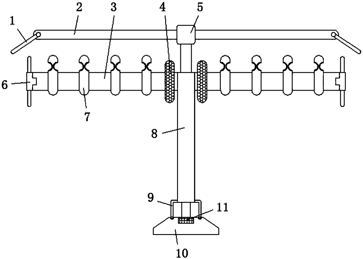
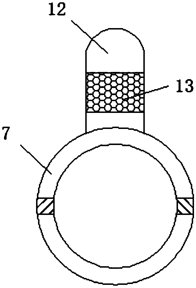
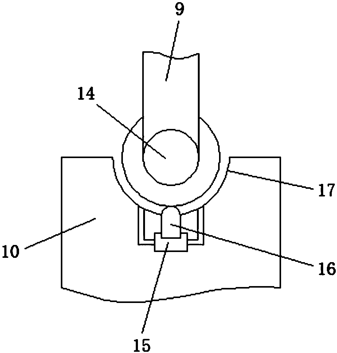
[0022] refer to Figure 1-3 , a storage rack for molybdenum rod electric heating elements, including a support column 8, the top of the support column 8 is sleeved with a sleeve 5, and the outer wall of the sleeve 5 is welded with a top plate 2, and the outer wall of the support column 8 is welded at an equal angle There is a hanger 3, the surface of the hanger 3 and one end close to the support column 8 is sleeved with an inner ring limit ring 4, and the surface of the hanger 3 and one end far away from the support column 8 is clamped with an outer ring limit ring 6. The surface of the frame 3 is equidistantly sleeved with a partition ring 7 between the inner ring s...


PUM


Abstract

The invention discloses a placing frame for storing a molybdenum rod electric heating element. The frame comprises a supporting column, a sleeve pipe sleeves the top of the supporting column, and a top plate is welded to the outer surface wall of the sleeve pipe; hanging frames are welded to the outer surface wall of the supporting column in an equal-angle mode, one end, close to the supporting column, of the surface of the hanging frames is sleeved with an inner ring limiting ring, and the bottom of the supporting column is rotationally connected with a base through a transmission shaft; andauxiliary supporting rods are symmetrically welded at the bottom ends of the outer surfaces of the two sides of the supporting column, moreover, the bottom end of auxiliary supporting rods are connected with a groove in the upper surface of the base through limiting sliding wheels in a sliding mode, an oil storage bin is arranged inside the base and located below the groove, and a pressing block is arranged above the oil storage bin. According to the frame, the supporting column is simple and reasonable in overall structural design, the supporting column can be horizontally operated in a rotation mode through a bearing, so that the placing angles of the hanging frames can be changed, so that people can be prevented from placing the molybdenum rod heating element by walking, and the workload of workers is further reduced.

Description

technical field [0001] The invention relates to the technical field of molybdenum rod storage, in particular to a storage rack for electric heating elements of molybdenum rods. Background technique [0002] Molybdenum rods have a high melting point, good thermal conductivity and low thermal expansion properties, and can be used to manufacture electric vacuum devices and electric light source parts, and can also be used as high-temperature heating elements, high-temperature structural parts, electrodes, etc., while molybdenum rods are used as silicon-molybdenum rods One of the important components of the heating element, in the process of production and processing, it is necessary to use a placement rack to store and place the molybdenum rod heating element, so as to facilitate the movement and transportation of the molybdenum rod heating element. [0003] However, the existing molybdenum rod heating element storage rack has some shortcomings during use. On the one hand, the ...

Claims


Application Information

Patent Timeline
Patent Type & Authority Applications(China)
IPC IPC(8): B65D61/00B65D85/86
CPCB65D61/00B65D2585/86
Inventor 刘庭富
Owner SICHUAN S Y MOLY TECH CO LTD
Learn More